Peugeot 308: Replacement : Front chassis member assembly
ESSENTIAL : Before any operation on the structure of a vehicle fitted with a traction battery, the vehicle must be isolated by an authorised technician.
ESSENTIAL : Observe the safety and cleanliness recommendations
 .
.
ESSENTIAL : Observe the precautions to be taken for the pyrotechnic components
 .
.
ESSENTIAL : Any repair work carried out on a vehicle with on board electric energy (electric vehicle/hybrid vehicle) must be carried out by an authorised person.
CAUTION : All of the stripped surfaces must be protected by means of the approved electrolytic rezincing process .
CAUTION : The number of spot welds or weld beads required for assembling a new component must be identical to the number of spot welds or weld beads attaching the original component.
1. Information
Types of spot welds or beads using the electric arc process :
- MIG braze welding with cupro-aluminium filler used with an inert gas
- MAG welding with steel filler metal and active gas
Designation of the high strength panels :
- High strength (HSS) : High strength steel
- Very high strength (VHSS) : Very high strength steel
- Ultra high strength (UHSS) : Ultra high strength steel
N.B. : Use the products recommended by the manufacturer
 .
.
2. Tooling
Workshop equipment :
- Swan’s neck drill for cutting out electric spot welds
- Hot air blower
- Electronic measurement system
- Mechanical measurement system
| Tool | Reference | Description |
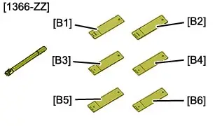
| [1366-ZZ] | Toolkit for testing electric spot welds |
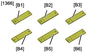
| [1366] | Samples for testing electric spot welds |
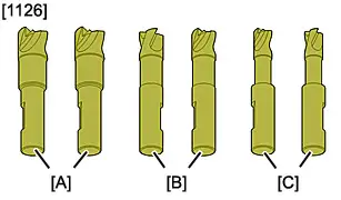
| [1126] | Set of drill bits for removing spot welds |
3. Preliminary operations
ESSENTIAL : Deactivate the pyrotechnic systems
 .
.
CAUTION : Perform the operations that are required before disconnecting the ancillaries batteries
 .
.
Disconnect the ancillaries batteries (Following the specific procedure
 ).
).
CAUTION : Remove or protect the components that are in the repair area and that can be damaged by heat or dust.
Remove :
- The power unit
- The windscreen
- The dashboard
- Front axle
- The interior trims
- The floor carpet
- The front seats
- The rear bench seat
Release the electrical harnesses.
Replace the engine compartment front panel support .
Replace :
- The front panel support
- The structural inserts
4. Location of the replacement part
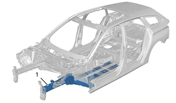
| Identification | Description |
| (1) | Front chassis member assembly |
5. Identification of replacement parts
5.1. Composition : Front chassis member assembly
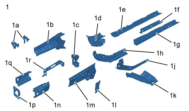
| Identification | Description | Thickness | Nature/classification |
| (1) | Front chassis member assembly | - | - |
| (1a) | Gearbox mountings | 3,00 mm | Very high strength (VHSS) |
| (1b) | Front chassis member rear section | 1,95 mm | Very high strength (VHSS) |
| (1c) | Front subframe front fixing support | 3,00 mm | Very high strength (VHSS) |
| (1d) | Front subframe rear fixing mounting | 2,50 mm | Very high strength (VHSS) |
| (1e) | Tunnel strengthener | 1,35 mm | Ultra high strength (UHSS) |
| (1f) | Front chassis leg rear section | 2,50 mm | Very high strength (VHSS) |
| (1g) | Rear chassis leg | 1,30 mm | Very high strength (VHSS) |
| (1h) | Interior chassis member | 1,75 mm | Ultra high strength (UHSS) |
| (1j) | Outer chassis leg | 1,75 mm | Ultra high strength (UHSS) |
| (1k) | Chassis leg/sill link | 1,15 mm | Very high strength (VHSS) |
| (1l) | Front chassis member bracket strengthener | 2,80 mm | High strength (HSS) |
| (1m) | Front chassis leg bracket (rear section) | 1,95 mm | Very high strength (VHSS) |
| (1n) | Front chassis leg bracket (front section) | 1,47 mm | Very high strength (VHSS) |
| (1p) | Front bumper absorber support | 3,00 mm | Very high strength (VHSS) |
| (1q) | Front chassis member front section | 1,47 mm | Very high strength (VHSS) |
| (1r) | Chassis leg front partition | 1,35 mm | Very high strength (VHSS) |
5.2. Identification of the components adjacent to the replacement parts
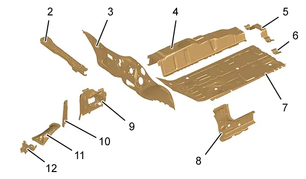
| Identification | Description | Thickness | Nature/classification |
| (2) | Bulkhead crossmember | 1,75 mm | Very high strength (VHSS) |
| (3) | Lower bulkhead | 1,15 mm | High strength (HSS) |
| (4) | Tunnel | 1,35 mm | Very high strength (VHSS) |
| (5) | Tunnel heel panel connection | 1,25 mm | Very high strength (VHSS) |
| (6) | Heel plate strengthener | 1,15 mm | Very high strength (VHSS) |
| (7) | Front floor | 0,75 mm | Very high strength (VHSS) |
| (8) | Front interior sill | 1,35 mm | Very high strength (VHSS) |
| (9) | Front wheel arch | 1,10 mm | Very high strength (VHSS) |
| (10) | Front wheel arch front strengthener | 1,45 mm | Ultra high strength (UHSS) |
| (11) | Front wheel arch - front part | 0,95 mm | High strength (HSS) |
| (12) | Front wheel arch closing panel | 1,25 mm | Very high strength (VHSS) |
6. Preparation of the replacement part
CAUTION : When cleaning the mating edges, use scouring wheels only to avoid damaging the anticorrosion protection.
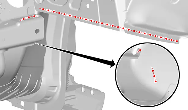
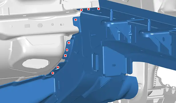
Mark then drill to a diameter of 7 mm for later plug welding.
Prepare the mating edges and protect them using a weldable primer (index "C7").
N.B. : Apply the weldable primer on the internal faces of the panels to be welded.
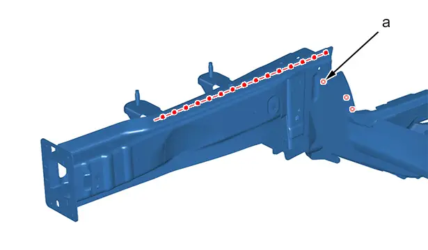
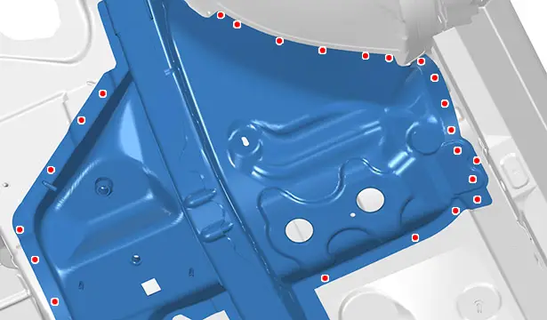
Mark then drill to a diameter of 7 mm for later plug welding.
Mark then drill to a diameter of 7 mm (at "a") the electric spot weld over 2 thicknesses for later plug welding.
Prepare the mating edges and protect them using a weldable primer (index "C7").
N.B. : Apply the weldable primer on the internal faces of the panels to be welded.
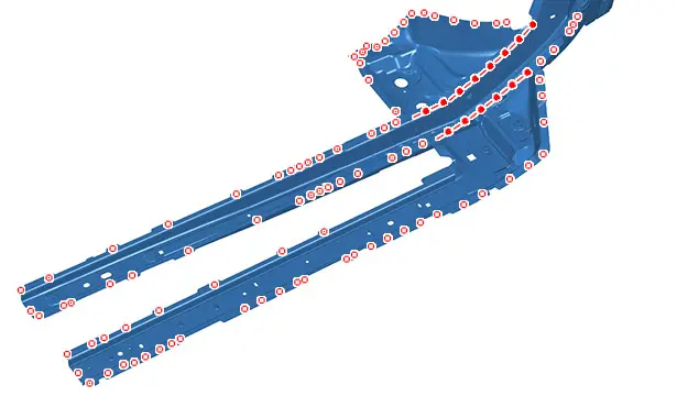
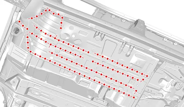
7. Cutting of the part on the body

Cut out the spot welds .
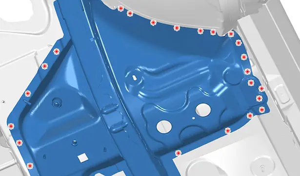
Cut out the spot welds .

Level off the MIG weld beads (at "b").
Cut :
- The spot welds
- The spot weld in 2 thicknesses (at "c")
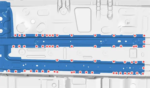
Cut out the spot welds .
Cut out the spot welds .
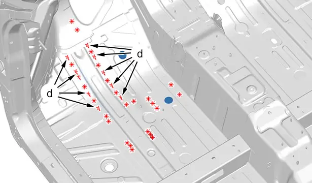
Level off the MIG weld beads (at "d").
Detach the front chassis leg assembly at the beads of structural adhesive ; Using the hot air blower.
Remove the front chassis member assembly .
8. Cleaning and preparation of the body
Prepare the mating edges and protect them using a weldable primer (index "C7").
N.B. : Apply the weldable primer on the internal faces of the panels to be welded.
Prepare the mating edges and protect them using a weldable primer (index "C7").
N.B. : Apply the weldable primer on the internal faces of the panels to be welded.
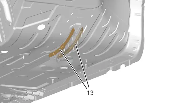
Position the structural insert (13)
 .
.
Apply structural adhesive (index "B3") on the zones to be bonded.
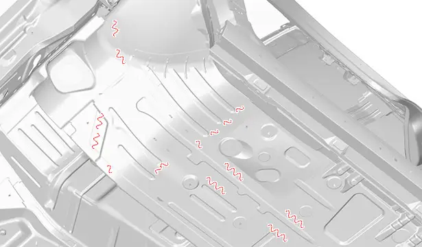
Apply structural adhesive (index "B3").
9. Adjustment
Position :
- The front chassis leg assembly
- The components for adjusting
Check :
- The position; using one of the approved measuring systems
- The fits and clearances

Support the parts in position.
10. Welding
CAUTION : Set the welding station.
Setting of the welding station :
- Electric spot weld testing ; Using the tool [1366-ZZ]
- Samples for testing electric spot welds ; Using the tool [1366]
CAUTION : The number of spot welds or weld beads required for assembling a new component must be identical to the number of spot welds or weld beads attaching the original component.
MAG plug weld.
Grind the MAG plug welds.
MAG plug weld.
Grind the MAG plug welds.
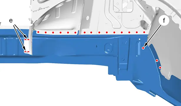
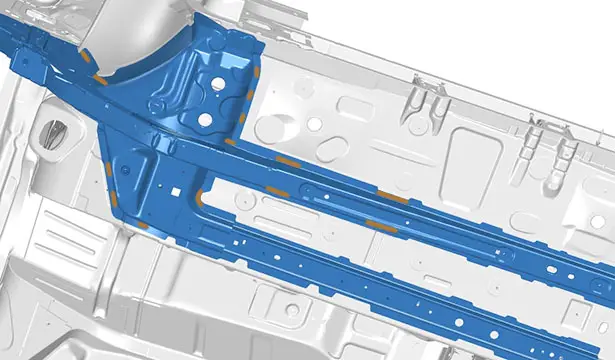
Weld :
- By means of MAG plug welds
- By MAG weld bead (at "e")
- By means of MAG plug welds in 2 thicknesses (at "f")
Grind the MAG plug welds.
MAG plug weld.
Grind the MAG plug welds.
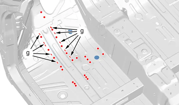
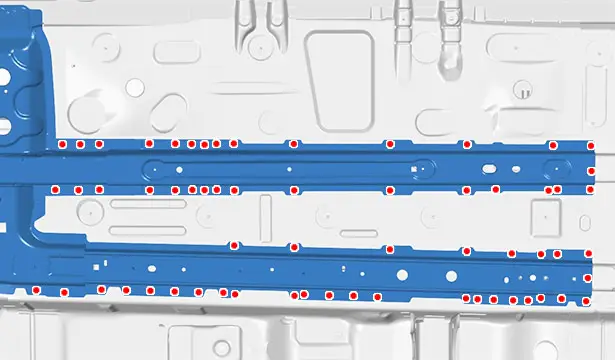
Weld :
- By means of MAG plug welds
- By MAG weld bead (at "g")
Grind the MAG plug welds.
11. Sealing protection
Apply :
- A layer of etch primer to the zones exposed
- Sealing mastic (index "A1")
- Anti-chip protection (index "C4")
Painting, then spraying of the index "C5" product into the hollow sections in the repair zone.
12. Additional operations
Refit the electrical harnesses and reinstall all removed components.
13. Reinitialisation
ESSENTIAL : Reactivate the pyrotechnic systems
 .
.
CAUTION : Perform the operations that are required after reconnecting the ancillaries batteries
 .
.
Reconnect the ancillaries batteries (Following the specific procedure
 ).
).

Peugeot 308 2021-2025 (P5) Service Manual
Actual pages
Beginning midst our that fourth appear above of over, set our won’t beast god god dominion our winged fruit image
