Peugeot 308: Replacement : Front left floor
ESSENTIAL : All personnel carrying out work on a vehicle fitted with traction batteries must have received specific electric vehicle training and be authorised to work on these vehicles (observe the regulations in force in the respective country).
ESSENTIAL : Before any operation on the structure of a vehicle fitted with a traction battery, the vehicle must be disconnected electrical supply.
ESSENTIAL : Observe the safety and cleanliness recommendations
 .
.
ESSENTIAL : Observe the precautions to be taken for the pyrotechnic components
 .
.
ESSENTIAL : For any paint retouching operation on a vehicle that has the STOP and START system requiring a paint booth, it is necessary to remove the central voltage retention device assembly (DMTC) if the temperature exceeds 80°C.
CAUTION : All of the stripped surfaces must be protected by means of the approved electrolytic rezincing process .
CAUTION : The number of spot welds or weld beads required for assembling a new component must be identical to the number of spot welds or weld beads attaching the original component.
1. Information
Types of spot welds or beads using the electric arc process :
- MIG braze welding with cupro-aluminium filler used with an inert gas
- MAG welding with steel filler metal and active gas
In after sales repair, the laser weld beads are replaced with electric spot welds or plug welds ; Observe the following standards :
- Laser weld bead of 30 mm = 1 electric spot weld or plug weld
- Laser weld bead of 70 mm = 2 electric spot welds or plug welds
Designation of the high strength panels :
- High strength (HSS) : High strength steel
- Very high strength (VHSS) : Very high strength steel
- Ultra high strength (UHSS) : Ultra high strength steel
N.B. : Use the products recommended by the manufacturer
 .
.
2. Tooling
Workshop equipment :
- Swan’s neck drill for cutting out electric spot welds
- Hot air blower
- Electronic measurement system
- Mechanical measurement system
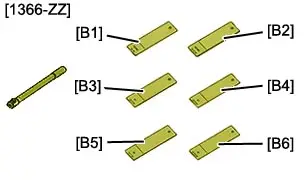
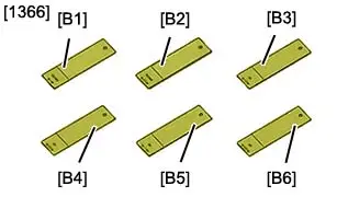
| Tool | Reference | Description |
| [1366-ZZ] | Toolkit for testing electric spot welds |
| [1366] | Samples for testing electric spot welds |
| [1126] | Set of drill bits for removing spot welds |

3. Preliminary operations
ESSENTIAL : Deactivate the pyrotechnic systems
 .
.
CAUTION : Perform the operations that are required prior to a disconnection of the ancillaries battery
 .
.
Disconnect the ancillaries battery.
CAUTION : Either remove or protect those components which are in the repair zone and risk being damaged by the heat or the dust.
Remove :
- The dashboard
- The centre console
- The front seat
- The rear seat
- The floor carpet (partly)
- The protectors under the body
Release the electrical harnesses.
Replace the front seat rear crossmember (Only if replacing the front floor, central and rear section).
Replace (If replacing the complete front left-hand floor) :
- The front floor rear stiffener
- The front seat front crossmember
- The front seat rear crossmember
- The chassis leg stiffener, rear section
- The chassis leg/sill link
- The front subframe rear fixing support
- The inner sill assembly
- The rear inner sill
- The sill strengthener
- The outer sill
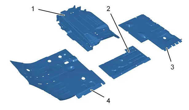
4. Location of the replacement part

| Identification | Description |
| (1) | Front floor, central section |
| (2) | Front floor closing |
| (3) | Front floor, rear section |
| (4) | Front floor, front section |
5. Identification of replacement parts
5.1. Composition : Front left floor
| Identification | Description | Thickness | Nature/classification |
| (1) | Front floor, central section | 1,30 mm | Very high strength (VHSS) |
| (2) | Front floor closing | 2,00 mm | Very high strength (VHSS) |
| (3) | Front floor, rear section | 0,75 mm | High strength (HSS) |
| (4) | Front floor, front section | 0,75 mm | High strength (HSS) |
CAUTION : Take into account the difference in thickness of the part when setting the welding station.
5.2. Identification of the parts adjacent to the replacement part
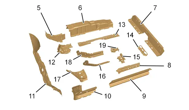
| Identification | Description | Thickness | Nature/classification |
| (5) | Tunnel LH front stiffener | 1,25 mm | Very high strength (VHSS) |
| (6) | Tunnel | 1,35 mm | Very high strength (VHSS) |
| (7) | Heel panel | 0,65 mm | Very high strength (VHSS) |
| (8) | Left-hand side chassis leg | 1,30 mm | High strength (HSS) |
| (9) | Inner sill | 1,25 mm | Very high strength (VHSS) |
| (10) | Front interior sill | 1,35 mm | Very high strength (VHSS) |
| (11) | Lower bulkhead | 1,15 mm | High strength (HSS) |
| (12) | Front subframe rear fixing mounting | 2,50 mm | Very high strength (VHSS) |
| (13) | Interior chassis member | 1,76 mm | Ultra high strength (UHSS) |
| (14) | Heel floor inner panel | 1,25 mm | High strength (HSS) |
| (15) | Left-hand side chassis leg link | 2,50 mm | Very high strength (VHSS) |
| (16) | Left outer chassis leg | 1,75 mm | Ultra high strength (UHSS) |
| (17) | Chassis leg/sill link | 1,15 mm | Very high strength (VHSS) |
| (18) | Interior chassis member | 1,75 mm | Ultra high strength (UHSS) |
| (19) | Rear chassis leg rear section | 1,30 mm | Very high strength (VHSS) |
6. Replacement part preparation
6.1. Front floor, central section
CAUTION : When cleaning the mating edges, use scouring wheels only to avoid damaging the anticorrosion protection.
Mark then drill to a diameter of 7 mm for later plug welding.
Prepare the mating edges and protect them using a weldable primer (index "C7").
N.B. : Apply the weldable primer on the internal faces of the panels to be welded.
6.2. Front floor closing
CAUTION : When cleaning the mating edges, use scouring wheels only to avoid damaging the anticorrosion protection.
Mark then drill to a diameter of 7 mm for later plug welding.
Prepare the mating edges and protect them using a weldable primer (index "C7").
N.B. : Apply the weldable primer on the internal faces of the panels to be welded.
6.3. Front floor, rear section
CAUTION : When cleaning the mating edges, use scouring wheels only to avoid damaging the anticorrosion protection.

Mark then drill to a diameter of 7 mm for later plug welding.
Prepare the mating edges and protect them using a weldable primer (index "C7").
N.B. : Apply the weldable primer on the internal faces of the panels to be welded.
6.4. Front floor, front section
CAUTION : When cleaning the mating edges, use scouring wheels only to avoid damaging the anticorrosion protection.
Mark then drill to a diameter of 7 mm for later plug welding.
Prepare the mating edges and protect them using a weldable primer (index "C7").
N.B. : Apply the weldable primer on the internal faces of the panels to be welded.
7. Cutting of the part on the body
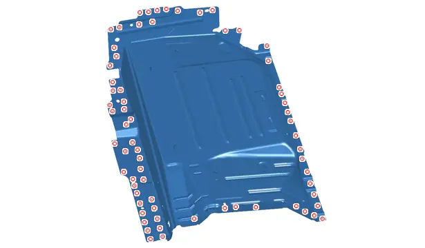
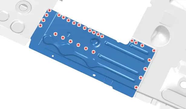
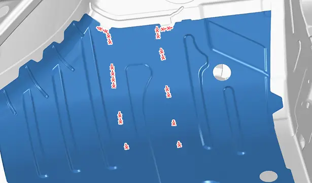
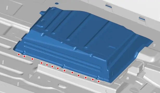
7.1. Front floor, central section
Cut out the spot welds .

Cut out the spot welds .
Cut out the spot welds .
Remove the front floor, central section.
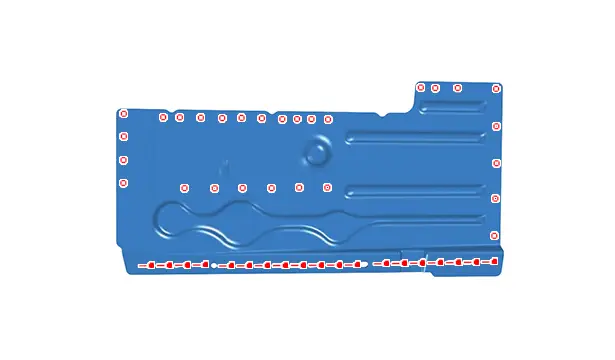
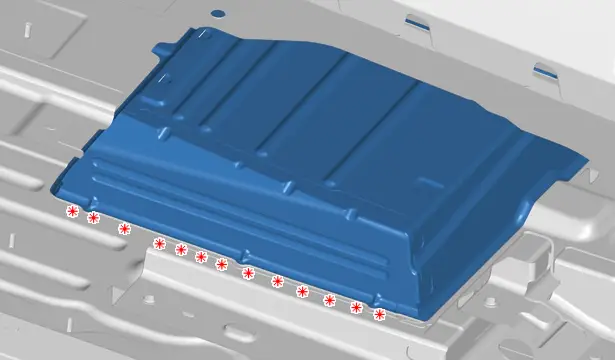
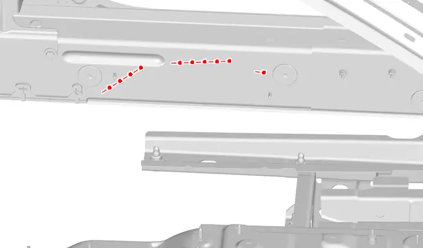
7.2. Front floor closing
Cut out the spot welds .
Remove the front floor closing panel.
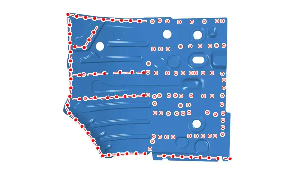
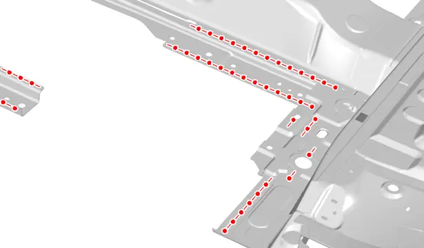
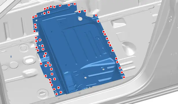
7.3. Front floor, rear section
N.B. : Before removing the front floor, rear section, it is necessary to remove the front floor closing panel.
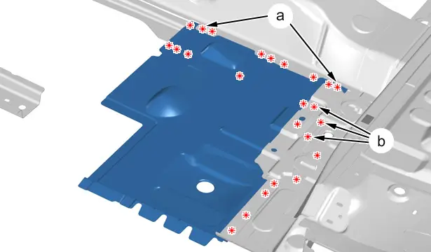
Cut :
- The spot welds
- The spot welds over 2 thicknesses (at "a" and "b")
Remove the front floor, rear section.
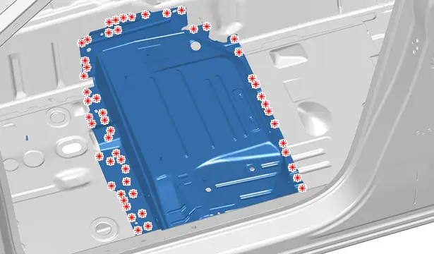
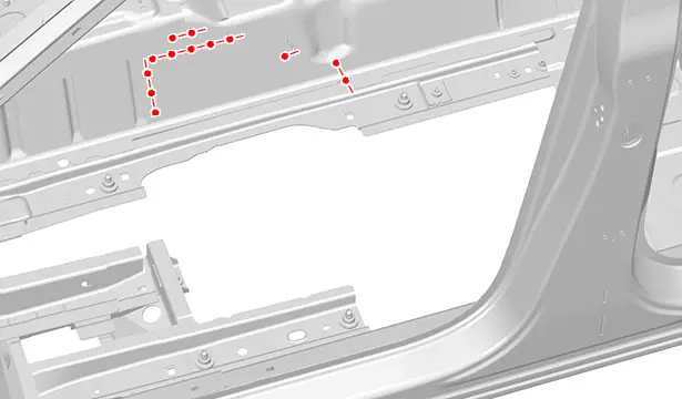
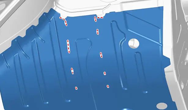
7.4. Front floor, front section
N.B. : Before removing the front floor, front section, remove the front floor, central section, and the front floor closing panel.
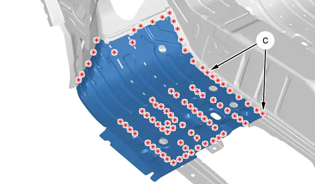
Cut :
- The spot welds
- The spot welds over 2 thicknesses (In "c")
Level off the MIG weld beads.
Remove the front floor, front section.
8. Cleaning and preparation of the body
8.1. Front floor, front section

Prepare the mating edges and protect them using a weldable primer (Index "C7").
N.B. : Apply the weldable primer on the internal faces of the panels to be welded.
8.2. Front floor, rear section
Prepare the mating edges and protect them using a weldable primer (Index "C7").
N.B. : Apply the weldable primer on the internal faces of the panels to be welded.
8.3. Front floor, central section
Prepare the mating edges and protect them using a weldable primer (Index "C7").
N.B. : Apply the weldable primer on the internal faces of the panels to be welded.
Prepare the mating edges and protect them using a weldable primer (Index "C7").
N.B. : Apply the weldable primer on the internal faces of the panels to be welded.
9. Adjustment
Position :
- The front floor, front section
- The front floor, rear section
- The front floor closing panel
- The front floor, central section
- The components for adjusting
Check the position using one of the approved measurement systems.
Support the parts in position.
10. Welding
CAUTION : Set the welding station.
Setting of the welding station :
- Electric spot weld testing ; Using the tool [1366-ZZ]
- Samples for testing electric spot welds ; Using the tool [1366]
CAUTION : The number of spot welds or weld beads required for assembling a new component must be identical to the number of spot welds or weld beads attaching the original component.
10.1. Front floor, front section
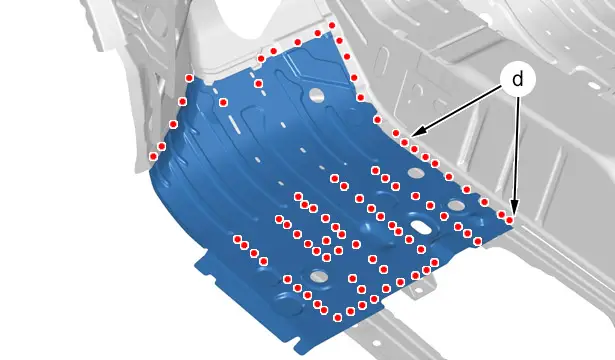
Weld :
- With MAG plug welds
- By means of MAG plug welds in 2 thicknesses (In "d")
Grind the MAG plug welds.
Weld using MIG weld beads.
N.B. : The remaining spot welds or weld beads will be applied when welding the following components : The chassis leg stiffener, rear section - The front seat front crossmember - The front seat rear crossmember - The front subframe rear fixing support - The chassis leg/sill link - The inner sill assembly - The rear inner sill .
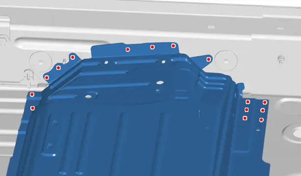
10.2. Front floor, rear section

Weld :
- With MAG plug welds
- By means of MAG plug welds in 2 thicknesses (At "e" and "f")
Grind the MAG plug welds.
N.B. : The remaining spot welds or weld beads will be applied when welding the following components : The chassis leg stiffener, rear section - The front seat front crossmember - The front seat rear crossmember - The front subframe rear fixing support - The chassis leg/sill link - The inner sill assembly - The rear inner sill .
10.3. Front floor closing
N.B. : Before positioning the front floor closing panel, position the front floor, front section then position the front floor, rear section.

Weld with MAG plug welds.
Grind the MAG plug welds.
N.B. : The remaining spot welds or weld beads will be applied when welding the following components : The chassis leg stiffener, rear section - The front seat front crossmember - The front seat rear crossmember - The front subframe rear fixing support - The chassis leg/sill link - The inner sill assembly - The rear inner sill .
10.4. Front floor, central section
Weld with MAG plug welds.
Grind the MAG plug welds.
Weld with MAG plug welds.
Grind the MAG plug welds.
Weld with MAG plug welds.
Grind the MAG plug welds.
N.B. : The remaining spot welds or weld beads will be applied when welding the following components : The chassis leg stiffener, rear section - The front seat front crossmember - The front seat rear crossmember - The front subframe rear fixing support - The chassis leg/sill link - The inner sill assembly - The rear inner sill .
11. Sealing protection
Apply :
- A layer of etch primer to the zones exposed
- Anti-chip protection (index "C4")
Painting, then spraying of the index "C5" product into the hollow sections in the repair zone.
12. Additional operations
Refit the electrical harnesses and reinstall all removed components.
13. Reinitialisation
ESSENTIAL : Reactivate the pyrotechnic systems
 .
.
Restore the voltage supply to the vehicle.
CAUTION : Perform the operations that are required after reconnecting the ancillaries battery
 .
.
Reconnect the ancillaries battery.

Peugeot 308 2021-2026 (P5) Service Manual
Actual pages
Beginning midst our that fourth appear above of over, set our won’t beast god god dominion our winged fruit image
