Peugeot 308: Repair : Electrical harnesses
The aim of this document is to define the rules for carrying out repairs or work on the electrical harnesses.
This document consists of 2 main parts :
- The first part describes the general repair methods
- The second part describes the circumstances of use of these methods in relation to the failures detected
1. Recommendations prior to carrying out the operation
The repairs must only be carried out by trained and authorised personnel.
ESSENTIAL : Only those personnel that have received training specific to electric vehicles are qualified to operate on the vehicle (observe the regulations in force in the respective country).
ESSENTIAL : Disconnect the battery before carrying out any repairs or work on an electrical harness (electric battery, ancillaries battery, traction battery, etc.).
ESSENTIAL : Take into account the manufacturer’s instructions before carrying out any work on the pyrotechnic functions (available on the computer equipment or on the marque’s technical information internet site.
2. Tooling
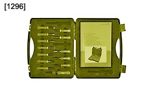
| tool | Reference | Description |
| [1296] | Connection repair kit |
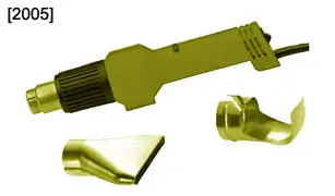
| [2005] | Warm air generator |
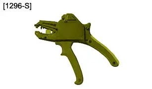
| [1296-S] | Wire strippers |
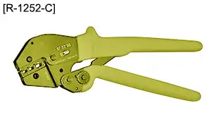
| [R-1252-C] | Crimping pliers |
3. Terminology
3.1. Usable wire
A wire is usable if its length is sufficient to permit repair without causing any tensile stress which could alter the sealing of the connection, the crimping resistance or result in a break over time (too taut).
N.B. : The wire is usable if its graspable length is more than 30 mm.
3.2. Unusable wire
A wire is unusable if its length is not sufficient to permit repair without causing tensile stress which could alter the sealing of the connection or result in a break over time (too taut).
A wire is unusable if it is stripped, pulled out, crushed over a considerable length or burnt.
N.B. : The wire is unusable if its graspable length is less than 30 mm.
4. General rules
General rules to be heeded :
- The repairs must only be carried out by trained and authorised personnel
- After repair, all of the electrical functions affected by the harness must be checked
- The connection of 2 conductors by tin soldering is prohibited (rigidity, breakage)
- The optical fibres and the screened wires must always be replaced if they are bent or broken
- After analysing the fault, eliminate its cause
- The twisted wires can be repaired
ESSENTIAL : Take into account the manufacturer’s instructions before carrying out any work on the pyrotechnic functions (available on the computer equipment or on the marque’s technical information internet site.
ESSENTIAL : All repairs or work on electrical harnesses are carried out with the battery disconnected (Including the service battery if present).
5. Repair procedures
5.1. Method for checking a wire
The aim of the wire checking method is to determine whether the repair can be carried out directly on the damaged wire or whether part of the wire must be replaced.
A wire is declared unusable in the following cases :
- The wire is not of sufficient length to permit repair without causing traction stresses which could alter the sealing of the connection or breakage over time (too taut)
- The wire is stripped, pulled out or crushed over a considerable length
- The wire is burnt
- In the case of a wire leaving an overmoulded connector, if the remaining usable length of wire is less than 30 mm
N.B. : In other cases, the wire is declared usable.
5.2. Method for selecting a wire
If a wire is unusable, the choice of the new wire to be used to carry out the repair must conform to the following characteristics :
- Cross-section of the wire
- Colour of the sleeve
ESSENTIAL : The cross-section of the wire must be equal to or larger than the initial cross-section, but never smaller.
N.B. : Depending on certain factors, a larger wire cross-section may cause interference or even a reduction in current.
It is compulsory for an earth cable to be green and yellow.
The other supply or information cables can be of a different colour.
N.B. : Favour the use of a cable of the same colour for the repair.
5.3. Method for stripping a wire
After cutting the wire, strip it without cutting the strands using approved wire strippers and observing the following lengths :
- 2,8 ± 0,5 mm for crimping of a clip or MQS tab
- 5 ± 1 mm for crimping of a clip or MQS tab
- 8 ± 1 mm for crimping a sleeve
- 15 ± 1 mm for an insertion in a sleeve
5.4. Method for tin soldering
Thestrengthening of a faulty crimp (electrical resistance too high) by tin soldering is permitted, observing the following procedure.
Tools required :
- Soldering iron with clean bit
- Tin 0,7 mm (60% tin 40% lead) with soldering flux without halogen
Method of operation :
- Melt a little tin on the iron bit
- Apply the iron bit under the crimp, the crimp wings must be visible
- Apply the tin wire to the copper strands at the end of the crimp (Soldering consumption approximately 3 mm)
N.B. : The times indicated are only valid for wires with a cross-section of 0,35 to 0,6 mm². For larger cross-sections, increase the time by 2 to 3 seconds.
CAUTION : It is important not to apply too much tin (risk of stiffening of the wire) to avoid damaging the wire insulation and the single-wire seals.
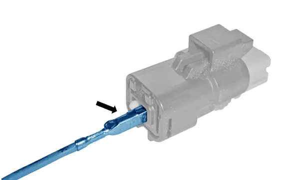
5.5. Method for unclipping a contact
ESSENTIAL : In extremely cold temperatures, the vehicle must be moved into a heated area and left to return to a temperature of approximately 20 °C before any work is carried out.
The contact must only be unclipped using the unclipping tool which is part of the approved kit and in accordance with instructions included.
CAUTION : Take care not to damage the seals, the contact cells, or the contacts to guarantee the sealing of the connector on refitting.
5.6. Method for selecting a contact
When replacing a contact or a spade terminal in a connector, it is imperative that the same components are used (gold-plated or tin-plated clip).
5.7. Method for positioning a contact in its cell
Positioning a contact :
- Visually analyse the condition of the contact
- Insert the contact in its cell
- Put the double lock back in place (depending on equipment)
- Pull the wire gently
CAUTION : If the contactis not retained in the cell, the connector must be replaced.
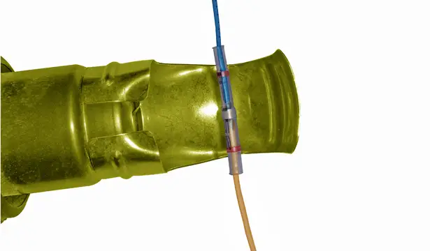
5.8. Method for applying a heat-shrink sleeve
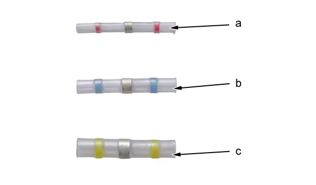
The heat-shrink sleeves must be chosen according to the cross-section of the wire to be repaired :
- "a" Red sleeve : Wire between 0,35 mm2 and 1 mm2
- "b" Blue sleeve : Wire between 1 mm2 and 3 mm2
- "c" Yellow sleeve : Wire between 3 mm2 and 5 mm2
N.B. : Crimp the heat-shrink sleeve using the tools and items in the connection repair kit. If the repair requires the use of several heat-shrink sleeves, stagger them to retain a minimal volume.
5.9. Simple repair (1 Heat-shrink sleeve )
CAUTION : To restore an electrical connection with a heat-shrink sleeve, use only the tools and items in the approved kit.
N.B. : Allow approximately 90 seconds for pre-heating of the hot air generator, one minute heating time depending on the cross-section of the wires and 3 minutes for cooling of the hot air generator.
Method of operation (Applicable for a repair of 1 or more wires) :
- Remove any covering from the wire (tape, sleeve, etc.)
- Cut and strip the end of each wire to be repaired ; Using the wire strippers
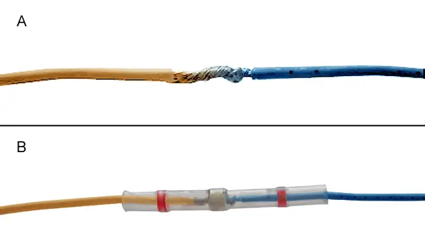
"A" Engage the stripped end of the 2 respective wires in the heat-shrink sleeve, twisting them.
"B" Support the 2 wires and assemble them by heating the sleeve ; Using the hot air generator (see table below).
| Diameter of wires | Hot air generator settings | Repair time |
| 2 mm2 wire cross section | Position 6Ventilation 1 | 30 seconds |
| 2 mm2 wire cross section | Position 4Ventilation 2 | 20 seconds |
| 0,5 mm2 wire cross section | Position 6Ventilation 1 | 20 seconds |
| 0,5 mm2 wire cross section | Position 4Ventilation 2 | 20 seconds |
Sideways movement of the hot air generator may be necessary to obtain uniform heating of the heat-shrink sleeve.
Put the contact in place in the connector.
Visually analyse the condition of the contact.
Insert the contact in its cell.
Gently pull on the wire to check that the contact is locked.
Restore the covering of the wire to guarantee protection at least identical to the existing protection.
N.B. : If the routing of the harness is modified, the harness must be clipped.
CAUTION : The tracks of a connector which are not connected electrically to the vehicle’s harness must be fitted with a connection wire and have an end cap fitted using the hot air generator.
CAUTION : If the repair requires the use of several heat-shrink sleeves, take care to stagger them to retain a minimal volume.
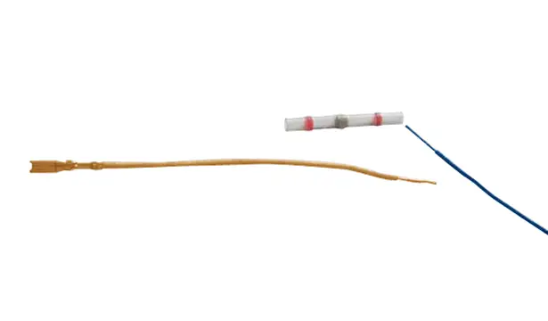
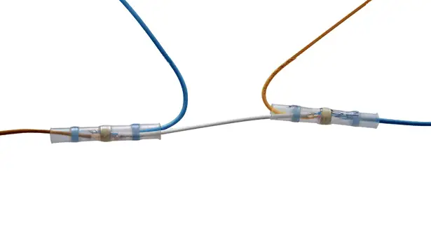
5.10. Repair using additional wires (2 heat-shrink sleeves), wire unusable
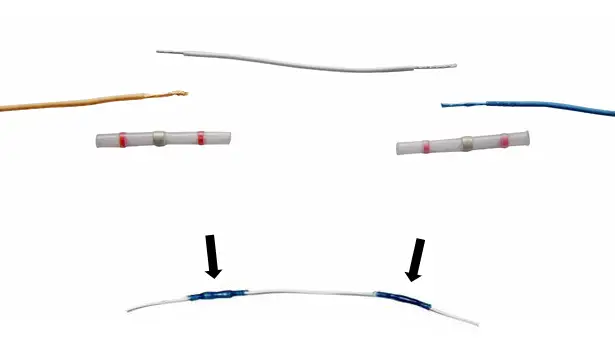
The heat-shrink sleeves must be chosen according to the cross-section of the wire to be repaired :
- Red sleeve : Wire between 0,35 mm2 and 1 mm2
- Blue sleeve : Wire between 1 mm2 and 3 mm2
- Yellow sleeve : Wire between 3 mm2 and 5 mm2
N.B. : Crimp a heat-shrink sleeve using the tools and items in the connection repair kitIf the repair requires the use of several heat-shrink sleeves, stagger them to retain a minimal volume.
Position the wires coming from one side in one sleeve and those coming from the other side in another sleeve taking care that the wires do not move away from each other.
To make it easier to insert the wires in the heat-shrink sleeve, turn the heat-shrink sleeve slightly.
Heat the sleeve using the hot air generator until the tin core melts and the surplus adhesive appears.
5.11. Method for applying a stitch weld sleeve
The heat-shrink sleeves must be chosen according to the cross-section of the wire to be repaired :
- Red sleeve : Wire between 0,35 mm2 and 1 mm2
- Blue sleeve : Wire between 1 mm2 and 3 mm2
- Yellow sleeve : Wire between 3 mm2 and 5 mm2
N.B. : Crimp the heat-shrink sleeve using the tools and items in the connection repair kit If the repair requires the use of several heat-shrink sleeves, stagger them to retain a minimal volume.
Position the wires coming from one side in one sleeve and those coming from the other side in another sleeve taking care that the wires do not move away from each other.
N.B. : Turn the heat-shrink sleeve slightly to insert the wires in the sleeve.
Heat the sleeve using the hot air generator until the tin core melts and the surplus adhesive appears.
Approximately 90 seconds must be allowed for pre-heating of the gun, 1 minute for heating according to the cross-section of the wires and 3 minutes for cooling of the gun.
5.12. Method for restoring the covering
In order to restorethe harness covering, guarantee protection at least identical to the existing protection.
If modifications are made to the routing, guarantee a minimum distance of 10 mm between the harness and its environment.
For the taped harnesses, place the repaired part flush against the body of the harness and tape the whole using adhesive tape.
In the case of plastic sleeves, place the repaired part flush against the body of the harness then replace the sleeving.
5.13. Method for selecting a protector
Mechanical protection : The mechanical protection is provided using a split spiral sleeve (Example : Engine compartment, Wheel arch).
Heat protection : The thermal protection is provided using a high temperature split spiral sleeve (Example : Near to the exhaust in the engine compartment).
Noise protection : The noise protection is provided using a sound deadening sleeve during reworking requiring simple or mechanical protection (Example : Passenger compartment, Tailgate).
5.14. Restoring the covering
In the case of changes to the routing, a distance of 10 mm minimum must be guaranteed between the harness and its surroundings. A positioning device is compulsory to guarantee the positioning and orientation.
Taped strands : Place the repaired part flush against the body of the harness and tape the whole using adhesive tape.
Sleeved strands : Place the repaired part flush against the body of the harness then put the sleeving back in place.
Closed sleeves : Avoid cutting the closed sleeves in order to permit passage of the wire, otherwise place the repaired wire on top with appropriate covering.
Open sleeves : It is compulsory to tape the openings after work.
5.15. Method for repairing the earth points
N.B. : In all cases, check the condition of the earth terminal contact/support/nut or bolt surface and clean it.
Several solutions are recommended.
Soldered square nut with broken self-tapping bolt or the thread of which is damaged :
- If the bolt can be extracted, remove it, drill and tap to M8 using a new M8 bolt then apply a tightening torque of 17 Nm ± 3 Nm
- If there is another earth nut nearby, extend the earth wire to reach this earth point, taking care to create a drip channel loop, Apply a tightening torque of 12 Nm ± 2 Nm
Stud which is badly soldered (TUCKER stud), broken or the thread of which is damaged :
- If the stud soldering has failed, re-solder the old stud by brazing
- If the thread is damaged or the bolt is broken, solder a new stud by brazing
In the 2 cases of soldering, apply the method below :
- Place a fire extinguisher near the work area
- Strip the location at which the pin is to be soldered
- Rotary sand the soldering location
- Solder the stud or the pin using the gun provided for this purpose
- Apply anticorrosion protection
- Put the removed components back in place
Soldered square nut with slackened self-tapping bolt :
- If the M6X100 self-tapping bolt is simply slack, retighten the bolt applying a tightening torque of 12 Nm ± 2 Nm
- If the bolt has to be removed, fit a new M6X100 self-tapping bolt, engage it manually in the existing thread (take care not to create a new thread) then apply a tightening torque of 12 Nm ± 2 Nm
Earth on the gearbox slackened : If the bolt M8x125 is simply slack, retighten by applying a tightening torque of 17 Nm ± 3 Nm.
6. Specificities : Hybrid vehicles
The harnesses of the 200 V network in hybrid vehicles can be repaired, with the exception of the shielded cable ; Replacement of the shielded cable is imperative if there is any damage to the cable or its connections.
ESSENTIAL : For the harnesses of the 200 V network, on hybrid vehicles (low voltage range of 50 V to 1000 V), the personnel must have the authorisation according to the type of operation of the publication UTE C 18-550.
If the reworking is carried out by a third party, a contract must be drawn up for the work between the supplier and the company that it employs, before the work is carried out.
ESSENTIAL : All work relating to the connectors and contacts must be carried out by qualified and trained personnel.
The wirer will take all measures necessary to avoid a change of personnel during the period of quality reworking in the reworking sector.
7. Failure detected / Circumstances of use
7.1. Wire broken
Apply the following methods in order :
- Method for checking a wire (5.1)
- Method for stripping a wire (5.3)
- Method for selecting a wire (5.2) (In the case of an unusable wire)
- Method for restoring the covering (5.12)
- Method for selecting a protector (5.13)
ESSENTIAL : If the wire is unusable, cut the wire at the accessible points (near the connectors) and apply section 4.1 observing 2 rules : Remain in the same harness, retain the numbering of the wires (Cut the wire in such a way as to retain the numbered ends).
ESSENTIAL : In the case of a vehicle under warranty, if more than 4 wires are cut, the harness must be replaced.
7.2. Burnt wire
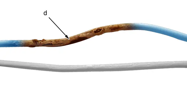
"d" Burnt wire.
Apply the following methods in order :
- Method for stripping a wire (5.3)
- Method for selecting a wire (5.2)
- Method for restoring the covering (5.12)
- Method for selecting a protector (5.13)
N.B. : Re-cut more than 5 cm from the hot point and strip the wires; check that there is no sign of burning in the stripped part of the wire.
CAUTION : After analysing the fault, eliminate its cause ; Check all of the vehicle functions, the blown fuses.
CAUTION : In the case of a vehicle under warranty, the harness must be replaced.
CAUTION : In the case of a vehicle which is not under warranty, if more than 4 wires are burnt, the harness must be replaced.
7.3. Missing wires in the harness
Apply the following methods in order :
- Method for selecting a wire (5.2)
- Method for selecting a contact (5.6)
- Method for selecting a protector (5.13)
7.4. Faulty splice
Apply the following methods in order :
- Method for stripping a wire (5.3)
- Method for selecting a wire (5.2)
- Method for applying a stitch weld sleeve (5.9)
- Method for selecting a protector (5.13)
ESSENTIAL : Cut the wire level with the splice.
7.5. Wire cut at the connector outlet / Contact unclipped or pulled out / Contact oxidised
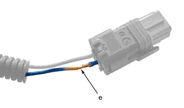
"e" Wire cut at the connector outlet.
7.5.1 - Pre-wired connector available from the Replacement Parts Department (Contact + wire assembly).
Apply the following methods in order :
- Method for unclipping a contact (5.5)
- Method for stripping a wire (5.3)
- Method for selecting a wire (5.2)
- Method for selecting a contact (5.6)
- Method for positioning a contact in its cell (5.7)
- Method for selecting a protector (5.13)
ESSENTIAL : If the contact is oxidised, replace the contact, create a low harness point at the connector outlet (modify the drip channel routing) and depending on the degree of oxidation, add grease in the connector (contact cleaner).
7.5.2 - Pre-wired connector available from the Replacement Parts Department.
Apply the following methods in order :
- Method for stripping a wire (5.3)
- Method for restoring the covering (5.12)
- Method for selecting a protector (5.13)
ESSENTIAL : If the contact is oxidised, replace the contact, create a low harness point at the connector outlet (modify the drip channel routing) and depending on the degree of oxidation, add grease in the connector (contact cleaner).
No component of the connector available from the Replacement Parts Department.
Replace the harness .
7.6. Wire cut at the overmoulded connector outlet
Apply the following methods in order :
- Method for checking a wire (5.1)
- Method for stripping a wire (5.3)
- Method for selecting a wire (5.2) (In the case of an unusable wire)
- Method for restoring the covering (5.12)
- Method for selecting a protector (5.13)
ESSENTIAL : If the wire is unusable and a passage hole is available, fit a grommet ; If an additional wire is available, use it and carry out the operations on each side of the overmoulded connector.
ESSENTIAL : If more than 4 wires are cut, the harness must be replaced.
7.7. Trapped wire
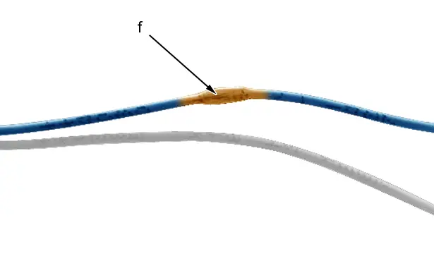
"f" Trapped wire.
Apply the following methods in order :
- Method for checking a wire (5.1)
- Method for stripping a wire (5.3)
- Method for selecting a wire (5.2) (In the case of an unusable wire)
- Method for restoring the covering (5.12)
- Method for selecting a protector (5.13)
ESSENTIAL : If the wire is unusable, cut the wire at the accessible points (near the connectors) and apply section 4.1 observing 2 rules : Remain in the same harness, retain the numbering of the wires (Cut the wire in such a way as to retain the numbered ends).
ESSENTIAL : If more than 4 wires are trapped, the harness must be replaced.
7.8. Stripped wire
Apply the method for selecting a protector (5.13).
7.9. Faulty crimping of a contact (Electrical resistance too high)
Apply the method for tin soldering (5.4).
7.10. Faulty earth point
Apply the method for repairing the earth points (5.14).

Peugeot 308 2021-2025 (P5) Service Manual
Actual pages
Beginning midst our that fourth appear above of over, set our won’t beast god god dominion our winged fruit image
