Peugeot 308: Replacement : Rear wing assembly
ESSENTIAL : All personnel carrying out work on a vehicle fitted with traction batteries must have received specific electric vehicle training and be authorised to work on these vehicles (observe the regulations in force in the respective country).
ESSENTIAL : Before any operation on the structure of a vehicle fitted with a traction battery, the vehicle must be disconnected electrical supply.
ESSENTIAL : Observe the safety and cleanliness recommendations
 .
.
ESSENTIAL : Observe the precautions to be taken for the pyrotechnic components
 .
.
CAUTION : All of the stripped surfaces must be protected by means of the approved electrolytic rezincing process .
CAUTION : The number of spot welds or weld beads required for assembling a new component must be identical to the number of spot welds or weld beads attaching the original component.
1. Information
Types of spot welds or beads using the electric arc process :
- MIG braze welding with cupro-aluminium filler used with an inert gas
- MAG welding with steel filler metal and active gas
Designation of the high strength panels :
- High strength (HSS) : High strength steel
- Very high strength (VHSS) : Very high strength steel
- Ultra high strength (UHSS) : Ultra high strength steel
N.B. : Use the products recommended by the manufacturer
 .
.
2. Tooling
Workshop equipment :
- Swan’s neck drill for cutting out electric spot welds
- Hot air blower
| Tool | Reference | Description |
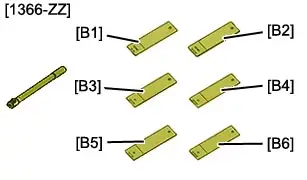
| [1366-ZZ] | Toolkit for testing electric spot welds |
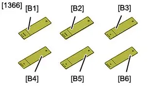
| [1366] | Samples for testing electric spot welds |
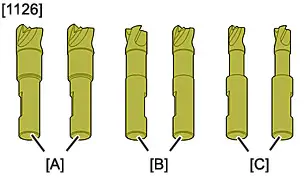
| [1126] | Set of drill bits for removing spot welds |
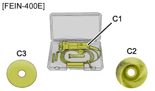
| [FEIN-400E] | "FEIN-400E" electric knife kit-"C1" electric knife-"C2" "FEIN" offset hub saw blade-"C3" Blade no. 103 |
3. Preliminary operations
ESSENTIAL : Deactivate the pyrotechnic systems
 .
.
CAUTION : Perform the operations that are required prior to a disconnection of the ancillaries battery
 .
.
Disconnect the ancillaries battery.
CAUTION : Either remove or protect those components which are in the repair zone and risk being damaged by the heat or the dust.
Remove :
- The boot trims
- The rear door aperture seal
- The fuel flap (depending on the side having the replacement)
- The rear seats
- The boot carpet
- The tailgate
- The rear bumper
- The headlining
- The interior trims
- The body sill plugs
- The panoramic sunroof (depending on equipment)
Release the electrical harnesses.
Replace :
- The roof(depending on equipment)
- The roof with panoramic sunroof (depending on equipment)
- The rear panel
- The rear quarter panel inner panel front expanding insert
- The rear wing inner panel lower expanding insert
- The rear quarter panel inner panel rear expanding insert
- The rear lamp housing expanding insert
- The rear lamp housing expanding insert (upper part)
- The rear pillar expanding insert
- The rear door striker fixing strengthener structural insert
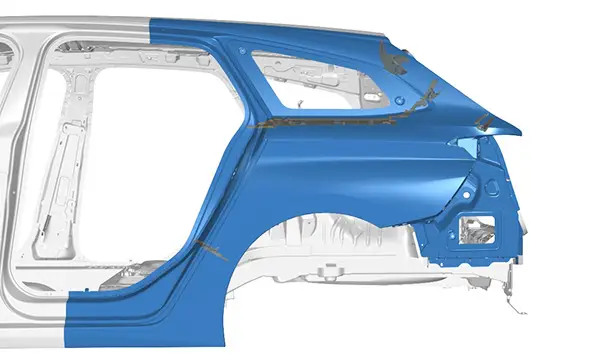
4. Location of the replacement part
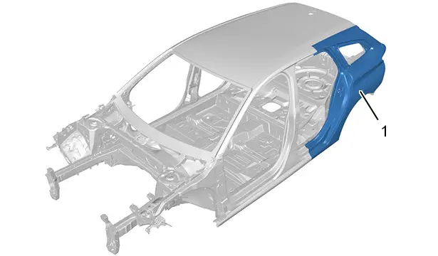
| Identification | Description |
| (1) | Rear wing assembly |
5. Identification of the replacement part
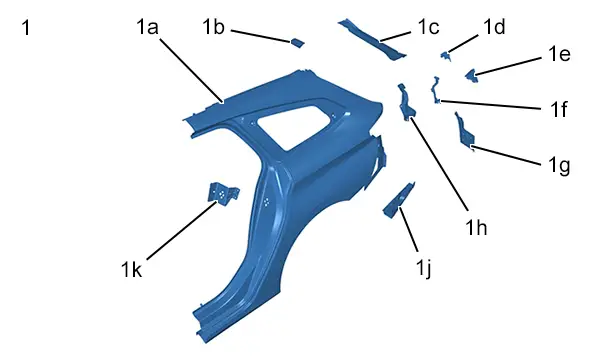
| Identification | Description | Thickness | Nature/classification |
| (1) | Rear wing assembly | - | - |
| (1a) | Rear wing | 0,64 mm | Mild steel |
| (1b) | Tailgate strut fixing strengthener | 1,45 mm | High strength (HSS) |
| (1c) | Tailgate aperture drip moulding | 0,65 mm | Mild steel |
| (1d) | Rear lamps housing expanding insert | - | - |
| (1e) | Rear lamps housing expanding insert | - | - |
| (1f) | Rear lamps housing expanding insert | - | - |
| (1g) | Rear light housing closing | 0,65 mm | Mild steel |
| (1h) | Rear lamp housing | 1,25 mm | Mild steel |
| (1j) | Rear wing lower closing panel | 0,65 mm | Mild steel |
| (1k) | Rear door striker fixing strengthener | 1,15 mm | High strength (HSS) |
CAUTION : Take into account the difference in thickness of the part when setting the welding station.
6. Identification of the parts adjacent to the replacement part
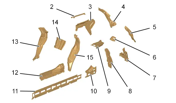
| Identification | Description | Thickness | Nature/classification |
| (2) | Rear wing inner panel top part | 0,95 mm | Mild steel |
| (3) | Quarter panel inner panel | 0,65 mm | Mild steel |
| (4) | Rear wing drip moulding gusset | 1,30 mm | Mild steel |
| (5) | Tailgate drip moulding inner panel | 0,65 mm | Mild steel |
| (6) | Rear pillar lower gusset | 0,97 mm | High strength (HSS) |
| (7) | Tailgate drip moulding lower inner panel | 1,47 mm | Mild steel |
| (8) | Rear wing inner panel rear part | 0,64 mm | Mild steel |
| (9) | Load floor extension | 0,80 mm | High strength (HSS) |
| (10) | Side member rear strengthener | 0,95 mm | Very high strength (VHSS) |
| (11) | Sill web | 0,95 mm | Ultra high strength (UHSS) |
| (12) | Rear interior sill | 1,35 mm | Very high strength (VHSS) |
| (13) | Lower quarter panel inner panel | 0,95 mm | Mild steel |
| (14) | ’C’ post stiffener | 0,95 mm | High strength (HSS) |
| (15) | Rear wing inner panel front part | 0,64 mm | Mild steel |
7. Preparation of the replacement part
CAUTION : When cleaning the mating edges, use scouring wheels only to avoid damaging the anticorrosion protection.
Prepare the mating edges and protect them using a weldable primer (index "C7").
N.B. : Apply the weldable primer on the internal faces of the panels to be welded.
Prepare the mating edges and protect them using a weldable primer (index "C7").
N.B. : Apply the weldable primer on the internal faces of the panels to be welded.
Prepare the mating edges and protect them using a weldable primer (index "C7").
N.B. : Apply the weldable primer on the internal faces of the panels to be welded.
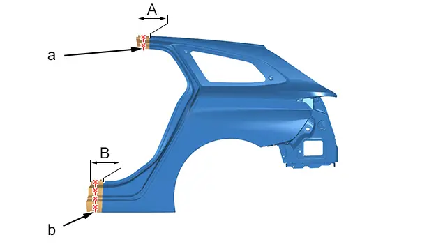
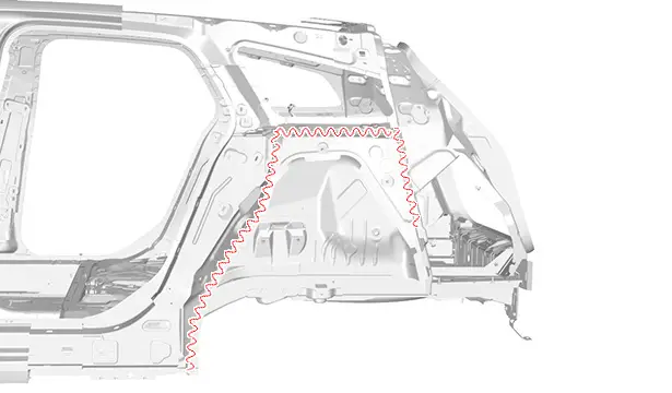
Draw a line (at "a","b") in the cutting zones "A","B" then cut out
 .
.
N.B. : The cutting lines "a" and "b" are given as a guide and may change depending on the different cases for replacing the rear wing assembly.
Prepare the mating edges and protect them using a weldable primer (index "C7").
Apply the weldable primer on the internal faces of the panels to be welded.
8. Cutting of the part on the body
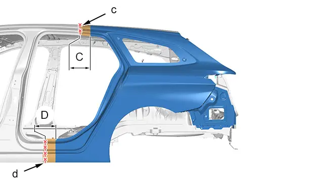
Draw a line (at "c","d") in the cutting zones "C","D" then cut out
 .
.
N.B. : The cutting lines "c" and "d" are given as a guide and may change depending on the different cases for replacing the rear wing assembly.

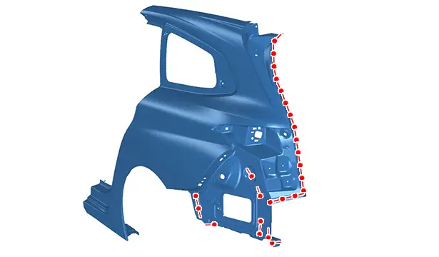
Cut out the spot welds .
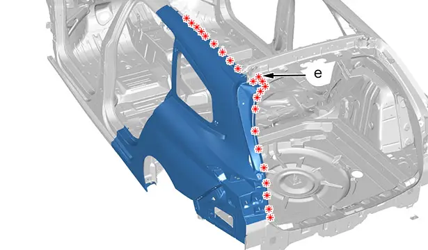
Cut :
- The spot welds
- The spot weld over 2 thicknesses (at "e")
Detach the rear wing assembly at the expanding inserts ; Using the hot air blower.
Remove the rear wing assembly.
9. Cleaning and preparation of the body
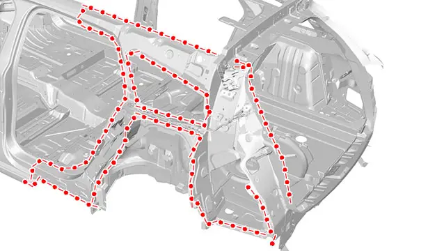
Prepare the mating edges and protect them using a weldable primer (index "C7").
N.B. : Apply the weldable primer on the internal faces of the panels to be welded.
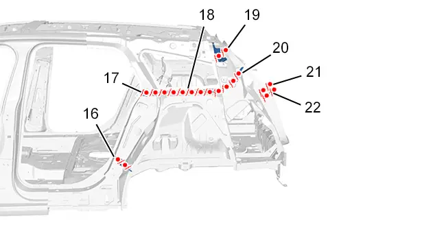
Seal the expanding inserts (16), (17), (18), (20), (21), (22).
Seal the structural insert (19).
Apply setting adhesive (index "A1").
Clip the structural insert.
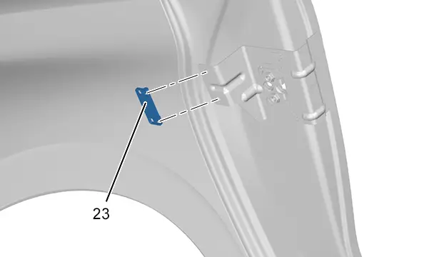
Seal the structural insert (23).
10. Adjustment
Position :
- The rear wing assembly
- The components for adjusting
Check the fits and clearances
 .
.
Clamp the part into position.
Adjust the cuts (if necessary).
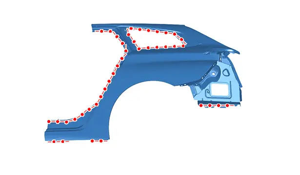
11. Welding
CAUTION : Set the welding station.
Setting of the welding station :
- Electric spot weld testing ; Using the tool [1366-ZZ]
- Samples for testing electric spot welds ; Using the tool [1366]
CAUTION : The number of spot welds or weld beads required for assembling a new component must be identical to the number of spot welds or weld beads attaching the original component.
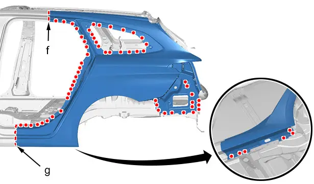
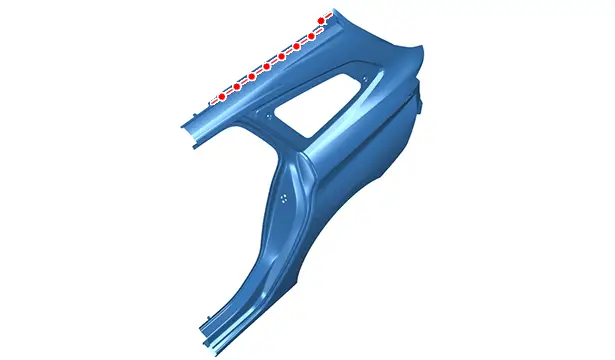
Weld :
- With MAG weld beads (at "f" and "g")
- With electric spot welds
Grind the MAG weld beads.

Weld :
- By means of MAG plug welds (at "h")
- With electric spot welds
Grind the MAG plug welds.
12. Sealing protection
Apply :
- A layer of etch primer to the zones exposed
- Sealing mastic (index "A1")
- Anti-chip protection (index "C4")
Painting, then spraying of the index "C5" product into the hollow sections in the repair zone.
13. Additional operations
Refit the electrical harnesses and reinstall all removed components.
14. Reinitialisation
ESSENTIAL : Reactivate the pyrotechnic systems
 .
.
Restore the voltage supply to the vehicle.
CAUTION : Perform the operations that are required after reconnecting the ancillaries battery
 .
.
Reconnect the ancillaries battery.

Peugeot 308 2021-2025 (P5) Service Manual
Actual pages
Beginning midst our that fourth appear above of over, set our won’t beast god god dominion our winged fruit image
