Peugeot 308: Repair : Traction battery internal components
ESSENTIAL : Observe the safety and cleanliness recommendations
 .
.
ESSENTIAL : All personnel carrying out work on a vehicle fitted with traction batteries must have received specific electric vehicle training and be authorised to work on these vehicles (observe the regulations in force in the respective country).
ESSENTIAL : Only the ("e-Expert Center" and "e-Repair Center") garages equipped to work on traction battery components are authorised to work on a damaged traction battery.
ESSENTIAL : Always insulate the loosened electric bar (busbar) terminals to prevent contact with the traction battery housing.
ESSENTIAL : To respond to the requirements of the directive 2023/1542/ EU, proceed as follows : After replacement or repair of an internal component of the traction battery (e.g. modules, junction box etc.), use Witech and read the required values which are marked with a “*”. The mandatory values (“*”) can be checked, captured and recorded at : https://stellantis2.my.salesforce.com/.
1. Safety recommendations
1.1. Absence of voltage check
Always perform an absence of voltage check on the traction battery before starting work on an internal component or on the power connectors.
Personal protective equipment must be used and appropriate procedures must be followed.
Depowering procedure for the traction battery :
- Description of the depowering procedure for the traction battery
- Description of the absence of voltage check on the traction battery
N.B. : If operations are not performed on certain areas of the traction battery, those areas must always be covered with an insulating carpet for voltages of up to 1000 V.
Recommendations relating to personal protective equipment :
- Wear safety goggles with appropriate side protectors when the user is within 15 m (50 feet) of the vehicle, whether inside or outside
- Wear insulated protective gloves certified to Class "0", checked and suitable for voltages of 1000 V and with leather protectors, whenever handling the traction battery - whether internally or externally, powered off or on
- Check and test the insulated protective gloves before use
CAUTION : Non-compliance with these procedures can lead to serious injury or even death.
1.2. Hazards related to the electric bar (busbar)
Unless the electric bar (busbar) is correctly installed in the traction battery, it can cause a short circuit.
A short circuit can cause an electric arc, resulting in splashes of molten metal.
To reduce the risk of serious or fatal injury and/or damage to the traction battery : Locate the current location of each electric bar (busbar) before removal and refit them only in their marked locations.
1.3. Tools
| Tool | Reference | Description |
| [WE190028A] | Personal protective equipment (PPE) |
| [WE0009J] | Insulated protective gloves certified to Class "0" |
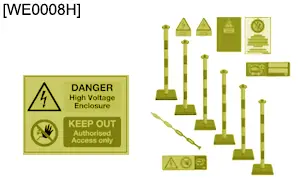
| [WE0008H] | Protection zone kit for electric vehicles |
| [WE0007G] | Body grab pole |
| [WE0006F] | Insulation bag |
2. General
2.1. Inside the traction battery
The traction battery is composed of 216 cells, divided into 17 modules.
Each module of the traction battery is :
- Equipped with 2 temperature sensors
- Cooled by an internal circuit for a performance and service life of 10 years
- Fixed to the base of the traction battery housing
The traction battery weighs a total of 350 kg.
The traction battery cover is screwed on and glued to protect the parts fixed to the base of the traction battery housing.
The rated voltage of the traction battery is between 376 and 433,5 V max.
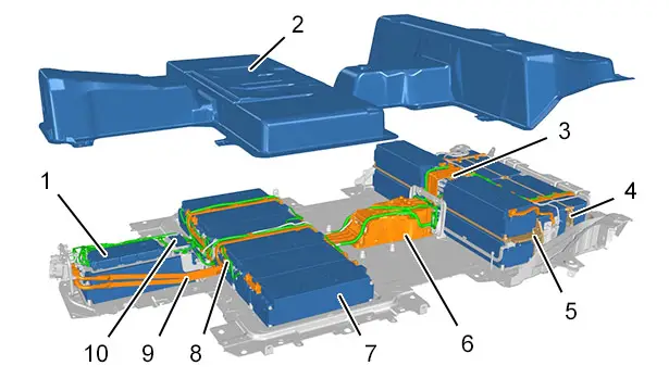
The traction battery is composed of the following :
- A traction battery (BMU) ECU (1)
- A traction battery cover (2)
- 7 control ECUs (3) for cells (CMC) in modules [1], [2], [3], [4], [5], [6], [7], [8], [9], [10], [12], [13], [14], [15] of the traction battery
- A cooling plate (4) for the traction battery modules [6], [7], [8], [9]
- A cooling plate (5) for the traction battery modules [1], [2], [3], [10]
- Of a junction box "H" (6)
- 17 modules (7) of the traction battery
- Electrical harnesses (8)
- Electric bars (busbar) (9)
- 2 control ECUs (10) for cells (CMC) in modules [16], [17], [18] of the traction battery
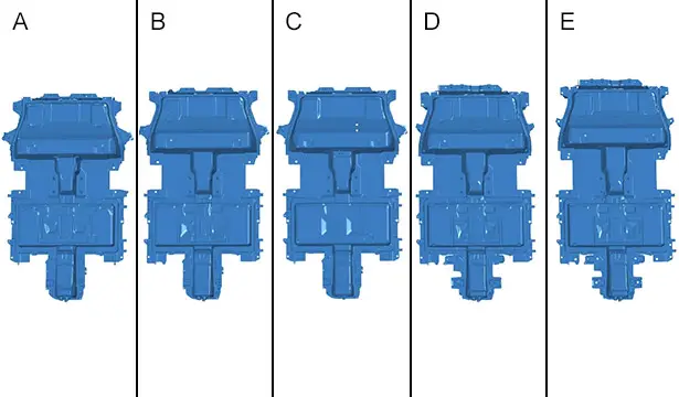
5 types of traction battery for the eCMP 2 platform.
| Identification | Type | Vehicle | Length (mm) | Width (mm) | Height ( mm) |
| "A " | eCMP L1 | eP2JO (Corsa-e), eP21 (208), eD34 (DS3), eP2QO (Mokka) | 2090 mm | 1280 mm | 280 mm |
| "B" | eCMP L2 V1 | eP24 (2008) | 2145 mm | 1280 mm | 280 mm |
| "C" | eCMP L2 V2 | eC41 (C4) | 2145 mm | 1280 mm | 280 mm |
| "D" | eDPE W1 L1 | eP51 (308), eOV51 (Astra) | 2145 mm | 1280 mm | 280 mm |
| "E" | eDPE W1 L2 | eP52 (308), eOV52 (Astra) | 2190 mm | 1280 mm | 280 mm |
2.2. Identification number of the traction battery (BIN)
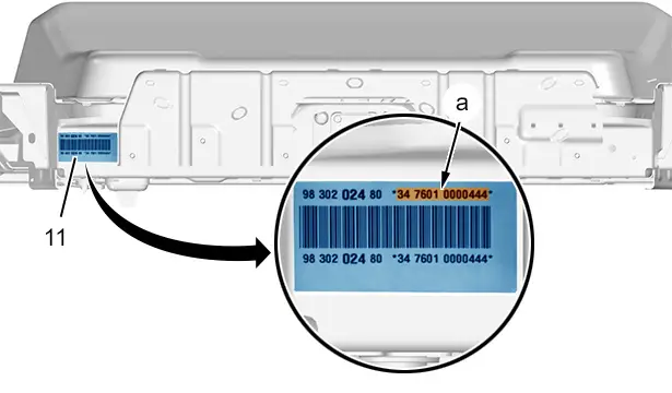
Each traction battery has an identification label (11) with its 13-digit identification number (In "a").
The identification label (11) is located at the back of the traction battery on the left-hand side and the identification number starts with "34 XXXX XXXXXXX " (In "a").
2.3. Information
Reduced traction battery performance in the following cases :
- If the cell temperature of a traction battery module is greater than 55°C
- If the voltage of the cells of a traction battery module is not between 2,5 and 4,2 V
- If the voltage of all 17 traction battery modules is greater than 433,5 V
- If the charge status (SOC) of the traction battery is not between 5% and 95%
2.4. Installation view of the traction battery modules
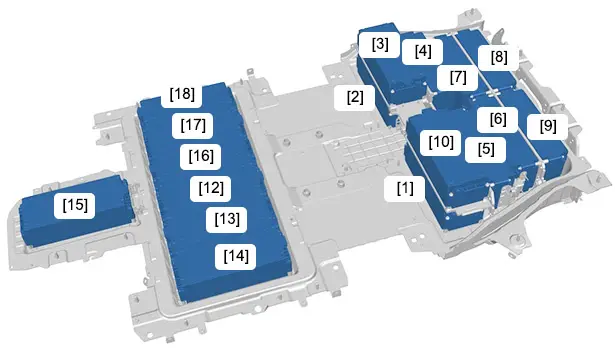
The modules have a "mechanical number" from to [1] with a predefined location.
The traction battery modules are cooled by a cooling plate in which the traction battery cooling circuit fluid circulates.
The traction battery modules are connected by electric bars (busbar).
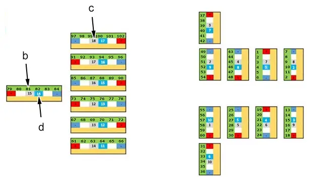
Each traction battery module is equipped with the following :
- 6 numbered cells (In "b")
- 2 numbered temperature sensors
- A "electrical number" (In "d")
- A "mechanical number" (In "c")
The management ECUs for the cells of the traction battery (CMC) are connected with a 12 V electrical harness.
There are 2 types of ECU (BMU) on the traction battery to influence the numbering of cells in modules of the traction battery :
- ECU "CATL" on which the numbering of cells is performed from 1 to 102
- ECU "BORGWARNER" on which the numbering of cells is performed from 0 to 101
| Mechanical number (In "c") | Electrical number (In "d") | Number of the management ECU for the cells of the traction battery (CMC) | Number of the cells of the traction battery ("CATL" ECU) (In "b") | Number of the cells of the traction battery ("BORGWARNER" ECU (In "b") |
| [1] | 10 | 5 | 55 to 60 | 54 to 59 |
| [2] | 9 | 5 | 49 to 54 | 48 to 53 |
| [3] | 7 | 4 | 37 to 42 | 36 to 41 |
| [4] | 8 | 4 | 43 to 48 | 42 to 47 |
| [5] | 5 | 3 | 25 to 30 | 24 to 29 |
| [6] | 4 | 2 | 19 to 24 | 18 to 23 |
| [7] | 1 | 1 | 1 to 6 | 0 to 5 |
| [8] | 2 | 1 | 7 to 12 | 6 to 11 |
| [9] | 3 | 2 | 13 to 18 | 12 to 17 |
| [10] | 6 | 3 | 31 to 36 | 30 to 35 |
| - | - | - | - | - |
| [12] | 13 | 7 | 73 to 78 | 72 to 77 |
| [13] | 12 | 6 | 67 to 72 | 66 to 71 |
| [14] | 11 | 6 | 61 to 66 | 60 to 65 |
| [15] | 14 | 7 | 79 to 84 | 78 to 83 |
| [16] | 15 | 8 | 85 to 90 | 84 to 89 |
| [17] | 16 | 8 | 91 to 96 | 90 to 95 |
| [18] | 17 | 9 | 97 to 102 | 96 to 101 |
2.5. Installation view of the electric bars (busbar)
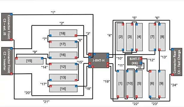
The electric bars "H" connect the modules, the traction battery ECU, the junction box (busbar) and the mounting plates of the front and rear connectors.
Each electric bar (busbar) has a predefined slot, as shown in the table below.
| Identification | Connections |
| "1" | Mounting plate in front of connectors / Junction box "H" |
| "2" | Mounting plate in front of connectors / Junction box "H" |
| "3" | Module [18] / Junction box "H" |
| "4" | Junction box "H" / Mounting plate behind connectors |
| "5" | Module [3] / Module [4] |
| "6" | Module [7] / Module [8] |
| "7" | Module [17] / Module [18] |
| "8" | Module [16] / Module [17] |
| "9" | Module [15] / Module [16] |
| "10" | Module [1] / Module [2] |
| "11" | Module [3] / Module [10] |
| "12" | (K6) relay housing / Module [6] |
| "13" | Module [8] / Module [9] |
| "14" | Module [12] / Module [15] |
| "15" | Module [12] / Module [13] |
| "16" | (K6) relay housing / Module [5] |
| "17" | Module [13] / Module [14] |
| "18" | Junction box "H" / Module [14] |
| "19" | Junction box "H" / Module [1] |
| "20" | Mounting plate in front of connectors / Junction box "H" |
| "21" | Mounting plate in front of connectors / Junction box "H" |
| "22" | Module [5] / Module [10] |
| "23" | Module [6] / Module [9] |
| "24" | Mounting plate behind connectors / Junction box "H" |
2.6. Installation view of the cooling plates and the thermal plates
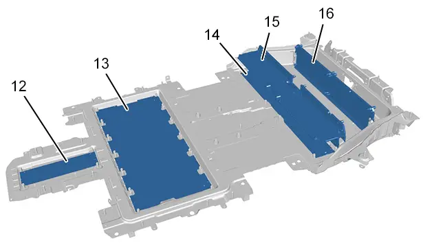
The traction battery modules are cooled with cooling plates :
- One cooling plate (12) for module [15] of the traction battery
- One cooling plate (13) for modules [12], [13], [14], [16], [17], [18] of the traction battery
- One cooling plate (14) for modules [1], [2] of the traction battery
- One cooling plate (15) for modules [3], [4], [5], [10] of the traction battery
- One cooling plate (16) for modules [6], [7], [8], [9] of the traction battery
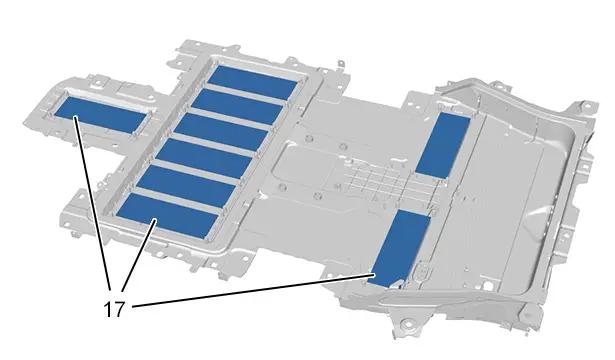
A thermal plate (17) is inserted between the traction battery modules and the cooling plates.
N.B. : If one of the traction battery modules is removed or replaced, the associated thermal plate (17) must be systematically replaced.
2.7. Storage temperature
Outside temperatures can limit the service life of the traction battery components : Store the traction battery at outside temperatures of max. 20°C.
Storing the traction battery at a constant outside temperature prevents the excessive deterioration of its components and subsequent reduction in their service life.
The traction battery’s service life depends on the outside storage temperature :
- From -40 to 20°C (10 year without restriction)
- From 20 to 25 °C (Less than 3 months)
- From 25 to 30°C (Less than 1 months)
- From 30 to 35°C (Less than 1 week)
- From 35 to 45°C (Less than 2 days)
Check the charge status (SOC) of the traction battery if the service life during storage is exceeded.
2.8. Storage
Recommended storage conditions for a "lithium-ion" traction battery :
- The traction battery should not be stored for longer than 24 months
- The traction battery ECU must be updated after storage
- The charge status (SOC) of the traction battery must be between 30% and 60% during the storage period
- After 1 year(s) of storage check that the traction battery’s charge status (SOC) is not less than 25%
- If the charge status (SOC) of the traction battery is less than 25%, the traction battery must be recharged
- The outdoor humidity level must be less than 90%
- Never place any external interfering loads on the traction battery during storage
3. On receiving the traction battery
3.1. Checks
After removing the traction battery from its packaging, check :
- The traction battery identification number (BIN) and register it
- If there are signs of fire, smoke or burn marks
- The underside of the traction battery for signs of an electrolyte leak (The electrolyte is more oily than water, emits a slightly sweet odour and causss coughing if inhaled)
- The age and charge status (SOC) of the traction battery
Clean the various components and check their condition and function :
- The cooling circuit (Leakage and flow rate)
- The electronic components (Functions and characteristic curves)
- The cover of the traction battery (Cracks and leakage)
- The electrical harnesses and electric bars (busbar) (Bends, cracks and breaks)
3.2. Replacement of parts
Only approved parts can be reconditioned. All refurbished parts must be checked before use (visual, dimensional and/or functional inspections) and meet the requirements of the original manufacturer.
If using non-original parts, the written approval of "STELLANTIS" After Sales-Service & Development engineer is required before they can be used.
4. Repair procedures
Reference documents :
- Precautions to be taken
 :Reduction in the voltage of the traction battery

- Leak diagnostics
 : Traction battery

- Check
 : Operations to carry out after repair

- Tightening torques
 : Traction battery internal components

- Removing - refitting
 : Traction battery cover

- Removing - refitting
 : Rear assembly of the traction battery modules, front section

- Removing - refitting
 : Rear assembly of the traction battery modules, rear section

- Removing - refitting
 : Traction battery modules

- Removing - refitting
 : Traction battery internal cooling plates

- Removing - refitting
 : Traction battery ECU

- Removing - refitting
 : Traction battery internal junction box

- Removing - refitting
 : Electrical harnesses inside the traction battery

- Removing - refitting
 : Fixing plates of the traction battery connectors


Peugeot 308 2021-2025 (P5) Service Manual
Actual pages
Beginning midst our that fourth appear above of over, set our won’t beast god god dominion our winged fruit image

