Peugeot 308: Organisation bulletin : Commercial launch - e-308 (eP5)
N.B. : This document is only valid for the initial launch. Future developments will not be updated.
This bulletin presents all the technical information required by authorised repairers and new vehicle and replacement parts distributors for the launch of the vehicle.
The presentation of this bulletin and its distribution are to be done by each departmental manager in the dealership :
- New vehicle sales : The sales manager must present this bulletin to all new vehicle sales staff and give them a copy
- Service : The service manager must present this bulletin to all service staff and give them a copy
- Replacement parts activity : The parts manager must present this bulletin to all parts staff and give them a copy
Main information and key points in the document : To be noted in particular.
CAUTION : Indirect tyre under-inflation detection - Reset the pressure of the tyres in the menu provided for this purpose on the multifunction touch screen whenever tyres are changed or their pressure is adjusted.
CAUTION : The purpose of the driving aid systems (ADAS: Advanced Driver Assistance System) is to make the vehicle safer to drive. To prevent any errors, the configuration can only be carried out automatically. The radar or camera adjustment conditions must comply with the recommended methods.
1. Presentation
1.1. Product
The e-308 is the second vehicle from the first electrification phase of the programme e-DPO (308 (P5)/ 408 (P6)/ ASTRA (OV5)/ C5X (E43)/ DS 4 (D41)).
The vehicle is manufactured at Mulhouse for all countries of sale.
The SW version will be launched 6 months later.
N.B. : e-DPO : Programme of electric vehicles built on the platform EMP2 V3 (Efficient Modular Platform 2 V3).
To be noted in particular : .
N.B. : No HIFI system available as standard or as an option on the electric vehicles.
N.B. : The towbar is only available as a factory option and cannot be fitted as an accessory.
Towbar :
- Does not allow towing (Trailer)
- Only suitable for a bicycle carrier (With a load limited to 80 kg)
Data
| - | Min | Max |
| Weight when empty | - | 1684 kg |
| Gross Vehicle Weight (GVW) | 2110 kg | 2190 kg |
| Maximum towing weight with load transfer | Prohibited | - |
| Permitted hitch weight | Prohibited | - |
| Boot volume | - | 1271 litres |
| Range (WLTP) | 413 km | - |

Commercial ranges : Consult the distance learning training module available on the PSA GROUP brand network training website.
Home ↦ VN/VO/B2B ↦ PEUGEOT vehicle range ↦ e-308 (eP5).
1.2. Marketed range - Identification
Commercial range: model code
 .
.
Identification
 .
.
Aftersales replacement parts label
 .
.
1.3. Presentation of the vehicle
Refer to the constructor’s technical documentation :
- Presentation of the vehicle

- Presentation of equipment

- Power trains

- Commercial launch
 : Electric drive train e-CMP (ELECTRIC COMMON MODULAR PLATFORM) (STEP 2)
 / Electric drive train e-DPE

- Tyres and equipment for winter

1.3.1. Dimensions
Refer to the handbook available on the manufacturer’s aftersales documentation portal.
Miscellaneous ↦Handbook pack ↦ e-308 (eP5).
N.B. : The vehicle handbook is the same for both internal combustion engine and electric vehicles.
1.3.2. Electronic architecture
This vehicle is equipped with the new NEA R1 electronic architecture (Electronic architecture identical to the internal combustion and PHEV versions).
Refer to the method : Presentation
 : Electric vehicle multiplexed architecture NEA R1
 .
.
1.3.3. Charging the traction battery
In the optimum phase of recommended charging (between 20 and 80%), the traction battery charge time is 27 minutes.
1.4. Accessory equipment and accessories
1.4.1. Accessory products
CAUTION : The fitting of the trailer towbar as an accessory is prohibited on this vehicle.
For detailed information about the products available, refer to the accessories catalogues on the manufacturer’s aftersales documentation portal.
Documentation ↦Accessory catalogue ↦Accessory section (Select the area in the central part of the screen).
1.4.2. Accessories diagnostics configuration
The fitting of the alarm requires configuration by selecting the "customer delivery" menu ; Using the diagnostic tool.
1.4.3. On-board radiocommunication transmitters fitted in Aftersales with aerial outside the vehicle (EEAV)
Recommendations/precautions
 : Guide for installation of the on-board radiocommunication transmitters fitted in Aftersales with aerial outside the vehicle (EEAV)
 .
.
2. Aftersales domain training courses
2.1. Distance learning modules
Distance learning modules are available on the website dedicated to the training courses of the brand networks.
Home ↦Aftersales ↦New ↦ e-308 (eP5) ….
2.2. Attended training courses
Attended training courses have been organised for the launch of the vehicle.
2.3. Hand-down kit
No hand-down kit is provided for this vehicle.
3. Aftersales documentation
The vehicle’s technical documentation can be consulted on the manufacturer’s Aftersales documentation portal :
- 1 month before the commercial launch : For the replacement parts catalogue, the new vehicle preparation and the initial principles of operation
- From the first commercial launch : For the repair methods and the repair time schedules
4. Diagnosis
As for all vehicles, the diagnostic tool must always have the latest update :
- Installation of the latest version
- Weekly check and installation of the latest updates via the internet
4.1. Diagnostic aids
The "Diagnostics aids", the tables of fault codes and the principles of operation can be consulted on the manufacturer’s Aftersales documentation portal.
Enter the VIN of the vehicle.
Documentation ↦Diagnosis (Left-hand menu) ↦ Function (Select the desired function in the central part of the screen) ↦ Diagnosis (Tab at the bottom of the screen) ↦ Pre-diagnosis.
These documents provide the following information :
- The customer symptoms and the processing methods
- The fault codes of the ECUs
- The suspect areas thought to be the cause of the fault
4.2. Diagnostic socket
Refer to the method : Diagnostic socket
 .
.
N.B. : The position of the diagnostic sockets differs according to left-hand or right-hand drive vehicles..
5. New vehicle preparation and static presentation of the vehicle (showroom mode)
5.1. New vehicle preparation
Observing the methods below makes it possible to perform the new vehicle preparation :
- Technical and aesthetic preparation of electric vehicles

- Deprotection of new vehicles

- Check of the ancillaries battery

- Position of the shunt for vehicle configuration to customer mode

- Safety and cleanliness precautions and recommendations

- Instructions for use of the E-XTEQ battery tester

N.B. : The new vehicle preparation must always be carried out using the diagnostic tool connected to the vehicle and connected to the Internet.
The main steps of the new vehicle preparation are :
- The vehicle conformity check
- The vehicle equipment conformity check
- Specific operations on tool kit : Clipping of the smoothing tool to the towing eye
- Bringing the vehicle to electronic conformity using the diagnostic tool including the 12 V battery check
- The technical checks such as the checks under the body and under the bonnet (*)
- The operational checks (lighting, heated seats, telematics, etc.) (*)
- The road test (*)
- The exterior deprotection and aesthetic preparation (Refer to the maintenance tips specified in the section "Handover of the vehicle")
- The interior deprotection and aesthetic preparation
N.B. : (*) According to the countries of sale of the vehicle.
The "Customer delivery" menu accessible from the diagnostic tool is used to carry out :
- New Vehicle Preparation
- The measurement of the traction battery charge status
5.2. Static presentation of the vehicle (showroom mode)
CAUTION : The vehicle must be set to showroom mode after the new vehicle preparation and the positioning of the shunt to the customer configuration.
The showroom mode makes it possible to enhance the vehicle displayed in the new vehicles showroom. The vehicle must be set to showroom mode by the new vehicle distributor :
- The built-in systems interface is set to showroom mode via the diagnostics menus ; Using the diagnostic tool
- External 12 V supply (approved by the manufacturer)
- A single recommended mode : Retaining of the 12 V battery in the vehicle
This equipment can be seen in the catalogues on the manufacturer’s Aftersales documentation portal : Organisation ↦Garage equipment catalogue ↦Diagnosis / Electricity group ↦Stabilised supply.
Details of the operations to be carried out to configure the vehicle to showroom mode are available on the manufacturer’s Aftersales documentation portal.
Static presentation of the vehicle
 : Configuration to showroom mode
 : e-308 (eP5)
 .
.
6. Maintenance
CAUTION : During servicing, the coolant must be topped up after checking that there are no leaks in the traction battery cooling circuit or internal leaks in the traction battery.
N.B. : To check that there are no internal leaks in the traction battery (read fault codes and check isolation) a diagnostic tool must be used and the traction battery cooling circuit sealing check method must be followed.
The maintenance conditions are described in the servicing schedule taken from the manufacturer’s Aftersales documentation portal and given to the customer on handover. The information relating to the maintenance conditions is available on the manufacturer’s Aftersales documentation portal.
Enter the VIN of the vehicle ↦Documentation ↦Technical documentation ↦Maintenance - Service schedules.
6.1. Service schedules
CAUTION : Only the servicing schedule on the manufacturer’s aftersales documentation portal is binding.
Enter the VIN of the vehicle ↦Documentation ↦Technical documentation ↦Maintenance - Service schedules.
| Normal (Europe) | Severe, and normal (serious conditions) | |
| Electrical | - Initial service : 1 year / 12 500 km | 1 year / 25 000 km |
| - Subsequent services : 2 years / 25 000 km |
Systematic operations :
- Servicing : Every 25 000 km or every 2 years
- Includes checking the efficiency of the air conditioning
- No traction battery SOH recalibration
Additional operations :
- Replacement of brake fluid : Every 2 years
- Replacement of the passenger compartment filter : Every 25 000 km or every 2 years
- Check the coolant pH : Every 15000 km or every 2 years
- Check of the headlamp adjustment : After 4 years then every 2 years
6.2. Configuration of the servicing schedule
On the diagnostic tool, the "Maintenance" menu permits access :
- To the servicing operations
- To the maintenance operations
- To the 12 V battery state of charge measuring operation
- When measuring the battery charge status
- The frequency of the servicing depends on the countries and the conditions of use. Refer to the organisation bulletin which covers this subject
6.3. Resetting of the service indicator
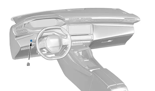
"a" Zero reset switch for the function selected (Service indicator or trip meter).
Maintenance indicator reset procedure (By means of the wipers stalk zero reset switch) :
- Switch off the ignition
- Press and hold the wipers stalk zero reset switch(at "a")
- Switch on the ignition : The distance recorder display begins a countdown
- When the display indicates "=0" : Release the button ; The spanner symbol disappears
For more information about this function, refer to the handbook on the manufacturer’s Aftersales documentation portal.
Documentation ↦Technical documentation ↦Miscellaneous ↦Handbook pack.
6.4. Reinitialisation of the indirect tyre under-inflation detection
Whenever a tyre is replaced or the pressure is adjusted, reinitialise the indirect tyre under-inflation detection function
 .
.
7. Repair
N.B. : LEV : Low Emission Vehicle - Low emission vehicles.
N.B. : PCDOV : PEUGEOT , CITROËN , DS, Vauxhall,Vauxhall.
7.1. Authorisation
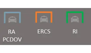
100% of authorised repairers can perform maintenance and repairs on LEV (low emission vehicles) according to 2 repairer levels.
N.B. : Traction batteries must be repaired at a specialist centre.
| Illustration | Level | Operator |
| Level 1: - All operations (maintenance, diagnostics, bodywork, etc.)- Except removal of the traction battery | : - Group’s authorised repairers (RA PCDOV) - Authorised repairers (Euro Repar Car Service (ERCS)) - Independent operators (RI) |
| Level 2: - Traction battery removal operations | e-REPAIR Center (RA PCDOV) |
| Traction battery repair centre | PSA GROUPE aftermarket |
As part of the aftersales network strategy applied to the new generation of LEV, certified "e-Expert Center" authorised repairers can perform all operations on electric and hybrid vehicles, including the removal and refitting of traction batteries.
The "e-Expert Center" label is issued subject to compliance with certification criteria primarily concerning :
- Aftersales staff training
- The installation of vehicle charging terminal(s) in the aftersales service workshop
- Tools and personal and team protective equipment
- Workstations including an isolation zone located outside the workshop for hazardous vehicles
- …
7.2. Strategy depending on market shares
Refer to the method : Commercial launch
 : Electric drive train e-CMP (ELECTRIC COMMON MODULAR PLATFORM) (STEP 2)
 / Electric drive train e-DPE
 .
.
7.3. 12 V battery disconnection - reconnection operations
Operations to be performed
 : Before disconnection and after reconnection of the ancillaries battery
 .
.
7.4. Body repair
7.4.1. Structure repair
ESSENTIAL : Lock out the vehicle before carrying out any bodywork repairs.
ESSENTIAL : Lock out the vehicle before carrying out any cutting, drilling, welding or painting. The functions of the traction circuit could be activated while the vehicle is in standby mode.
ESSENTIAL : During painting work, the temperature of the paint booth must not exceed 60°C with a maximum duration of 30 minutes if the traction battery is present in the vehicle.
CAUTION : The connections of the traction circuit (except the locked out electrical connectors) must be connected to prevent contamination of the contacts.
N.B. : Traction circuit: traction battery electrical network.
Refer to the methods :
- Body presentation

- Removal - refitting: bodywork components
7.4.2. Repair of exterior equipment
Refer to the methods :
- Body presentation

- Removal - refitting: equipment
7.5. Mechanical repair
CAUTION : In the case of a damaged vehicle or traction battery failure, refer to the specific procedure.
Perform the 3 following steps :
- 1 : Isolation of the vehicle outside in the area set aside for the visual and olfactory inspection
- 2 : Keep the vehicle in the isolation zone for further analysis and diagnostics
- 3 : Bring the vehicle into the workshop for removal of the traction battery once the previous 2 steps have been carried out and only if the vehicle presents no risk of thermal runaway
CAUTION : When an unsafe traction battery that is at risk of thermal runaway is removed, the removed traction battery must be stored in the exclusion area outside the workshop.
CAUTION : The vehicle must remain isolated for a period of one week.
N.B. : The repair process for traction batteries in the network is currently being developed . The repair procedures and replacement parts will be available shortly.
Refer to the methods :
- Mechanical presentation

- Removing - refitting : Mechanical components:
7.5.1. Specificities - Drain-refill-bleed the cooling system
The cooling circuit of the traction battery is filled and bled by vacuum draining and by controlling the 2 solenoid valves and the 3 circulation pumps using the diagnostic tool.
Refer to the method : Draining - filling - bleeding
 : Cooling circuit
 .
.
7.5.2. Replacement of the traction battery in a broken-down or damaged vehicle
Evaluate the dangerousness of the traction battery : Refer to the specific procedure.
7.5.3. Logistics of the traction battery
Refer to the specific procedure.
7.5.4. Circuit breaker connector (e-service plug)
ESSENTIAL : Lock out the vehicle to work on the traction circuit, as disconnecting the circuit breaker connector (e-service plug) is insufficient (Refer to the electrical lockout procedure available on the manufacturer’s aftersales documentation portal).
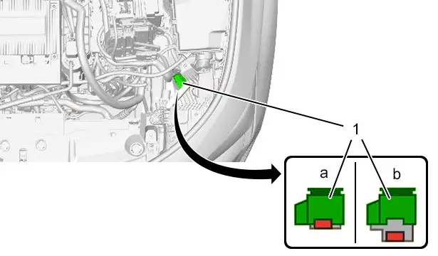
(1) Circuit breaker connector (e-service plug).
"a" Closed circuit position.
"b" Open circuit position.
The circuit breaker connector (e-service plug) makes it possible to open the relays of the traction battery to cut off the electrical supply.
7.6. Repair of equipment
Refer to the methods :
- Presentation of equipment

- Removing - refitting: equipment
8. Lifting - Immobilising - Towing
8.1. Lifting - Lifting - immobilising the vehicle
Refer to the method : Lifting - immobilising the vehicle
 .
.
8.2. Vehicle towing
Towing restrictions
| Front wheels on the ground | Rear wheels on the ground | All 4 wheels on the ground with a tow bar | On a lift |
| Prohibited | Authorised | Prohibited | Authorised |
CAUTION : For vehicles equipped with motorised brake calipers, towing with the rear wheels on the ground is only permitted with the electric parking brake unlocked or using "GoJacks".
CAUTION : In the case of electric vehicles, the repairer must have authorisation level B2XL.
Towing is by means of the "towing eye" installed under the boot floor :
- When the vehicle is towing another vehicle : Unclip the cover located on the right of the rear bumper and screw in the towing eye
- When the vehicle is towed by another vehicle : Unclip the cover located on the right of the front bumper grille and screw in the towing eye
The service manager must inform the roadside assistance providers to which they subcontract roadside assistance and towing of the special features of vehicle.
Refer to the method : Towing and lifting the vehicle.
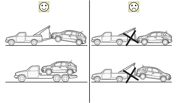
CAUTION : If an electric vehicle is towed on all 4 wheels, this must be carried out while driving at a speed of less than 4 km/h.
Refer to the methods : Precaution to be taken: towing an electric vehicle :
- For any towing, transport the vehicle on a platform or tow it with the front wheels lifted and the electric parking brake released
- If the electric parking brake cannot be released, transport the vehicle on a platform or tow it with the front wheels lifted and the rear wheels on "GoJacks"
- Towing the vehicle on all 4 wheels with a tow bar is prohibited (Risk of heat build-up and destruction of the electric drive train)
- It is prohibited for the repairer to tow the vehicle on all 4 wheels (Risk of heat build-up and destruction of the electric drive train)
In the workshop, without ancillary supply (12 V), the procedure for moving a broken-down vehicle is as follows.
Manually unlock the motorised brake calipers.
Manually unlock the park finger via the access door of the park finger locking actuator(80 revolutions).
CAUTION : Removing the park finger locking actuator means that it is not possible to unlock the park finger.
In the workshop, with ancillary supply (12 V), the various options for moving a broken-down vehicle are as follows.
With the front wheels lifted, and the electric parking brake released (According to the procedure described in the user manual ).
With all 4 wheels on the ground and a speed below 4 km/h, electric parking brake released and park finger unlocked.
N.B. : Refer to the various possible cases.
Before disconnecting the ancillaries battery (12 V) :
- Electric drive machine in neutral : The resistive torque at the electric drive machine outlet is approximately 1 N.m (Beyond 4,5 km/h, the electric drive machine inverter is at risk of being damaged )
- Motorised brake calipers unlocked : Unlocking the motorised brake calipers (According to the procedure described in the user manual )
- Park finger unlocked ; Park finger fuse removed from the built-in systems interface 12 before disconnecting the ancillaries battery (12 V)
Permanent positive only :
- Electric drive machine in neutral : The resistive torque at the electric drive machine outlet is approximately 1 N.m up to 3500 rpm(At approximately 40 km/h) . (Beyond 40 km/h, the electric drive machine inverter is at risk of being damaged )
- Motorised brake calipers unlocked : Unlocking the motorised brake calipers (According to the procedure described in the user manual )
- Park finger unlocked ; Park finger fuse removed from the built-in systems interface 12 before disconnecting the ancillaries battery (12 V)
Ignition positive :
- Electric drive machine in neutral : The resistive torque at the electric drive machine outlet is approximately 1 N.m up to 400 rpm(At approximately 4,5 km/h) . (Beyond 4,5 km/h, the electric drive machine inverter is at risk of being damaged )
- Motorised brake calipers unlocked : Unlocking the motorised brake calipers (According to the procedure described in the user manual )
- Park finger unlocked ; Park finger fuse removed from the built-in systems interface 12 before disconnecting the ancillaries battery (12 V)
+ starting :
- Electric drive machine in neutral : The resistive torque at the electric drive machine outlet is approximately 1 N.m up to 7000 rpm(At approximately 80 km/h) . (Beyond 4,5 km/h, the electric drive machine inverter is at risk of being damaged )
- Motorised brake calipers unlocked : Unlocking the motorised brake calipers (According to the procedure described in the user manual )
- Park finger unlocked ; Park finger fuse removed from the built-in systems interface 12 before disconnecting the ancillaries battery (12 V)
9. New tools
CAUTION : Use the appropriate tools and sleeves for the electrical harnesses with reduced diameter strands of 0,13 mm².
The existing tooling is continued.
9.1. Common tools for internal combustion and electric engines
Rear suspension positioning tool (1645183880).
Extraction tool for front hub carrier bearings (1636122180).
Azimuth adjustment tool for matrix headlamps (beam setter).
9.2. Lockout tools specific to electric engines (For level 1 and 2 authorised repairers)
On-board charger (OBC)/inverter cable.
Probe adapter.
9.3. Tools specific to the traction battery (For level 2 authorised repairers only)
Set of slings (1649259380).
Sling bars (1649258280).
Body centralisers (1644851580).
Traction battery/on-board charger (OBC) (9832667880) voltage measuring cable.
Traction battery handling kit (1644730580).
10. Warranty
Refer to the warranty manual (Warranty conditions).
N.B. : The brand may reduce the duration of the warranty or adapt the warranty costs in hot or very hot countries.
11. Recall campaigns
No special feature for this vehicle.
12. Escalation of customer incidents
Refer to the document "Organisation bulletin: feedback to customers" for the vehicle.
Manufacturer’s Aftersales documentation portal : "DOCUMENTATION" tab ↦Vehicle / General ↦Repair procedures ↦Data - Identifications.
13. Technical assistance
The "Dealer Issue Detection Assistance" (DID-A) is used to contact technical assistance.
Observe the DID standards (Manufacturer’s Aftersales documentation portal : "Incidents-Assistance" tab ↦DID practical information ↦DID standards) :
- Relevance standard
- Quality standard
N.B. : Refer to the organisation bulletin which covers this subject.

Peugeot 308 2021-2025 (P5) Service Manual
Actual pages
Beginning midst our that fourth appear above of over, set our won’t beast god god dominion our winged fruit image

