Peugeot 308: Procedure : Engine immobiliser breathalyser connection (NEA architecture)
ESSENTIAL : Observe the safety and cleanliness recommendations
 .
.
ESSENTIAL : All personnel carrying out work on a vehicle fitted with traction batteries must have received specific electric vehicle training and be authorised to work on these vehicles (observe the regulations in force in the respective country).
N.B. : The breathalyser connection complies with the UNE EN 50436-7 : 2016 standard.
N.B. : The breathalyser connection document includes information concerning the supplies by ancillaries battery, “CAN positive”, “ignition positive”, earthing and activation of the starter (Namely solution 3.1.a from the regulation EU 2021_1243).
N.B. : The breathalyser chosen for the installation must comply with European standards.
N.B. : The engine immobiliser breathalyser connection procedure is valid for left-hand drive and for right-hand drive.
Key : Operation symbols
 .
.
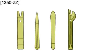
1. Tooling
Workshop equipment : Electrical harnesses tooling
 .
.
| Tool | Reference | Description |
| [1350-ZZ] | Stripping tools |
2. Preliminary operations
CAUTION : Perform the operations that are required before disconnecting the ancillaries batteries
 .
.
CAUTION : In the case of a vehicle with 2 batteries, carry out the specific operations for disconnecting and reconnecting the ancillaries batteries.
Disconnect the ancillaries battery or batteries (depending on equipment).
3. Prerequisite
A 5 A fuse must protect the breathalyser.
A relay integrated in the breathalyser must permit switching of the "START Authorisation" line, observe the following specifications :
- Switching voltage between 5,5 and 16 V
- Switched current between 10 and 50 mA
The breathalyser :
- Prevents starting of the vehicle if the regulations on alcohol consumption at the steering wheel are not complied with, in accordance with the countries of sale
- Must operate at a voltage of between 5,5 and 16 V (Starting and fluctuations of voltage linked with the Stop and Start)
- Must not consume more than 125 microamperes (ignition off for more than 2 minutes) under an ancillaries battery voltage of 12 V
- Must work with an exterior temperature of between - 40 and 85°C
N.B. : If these recommendations cannot be observed, the installer must advise the customer of this and not fit a breathalyser that does not observe the required specifications.
4. NEA architecture
The breathalyser is only fitted on the vehicles with :
- NEA architecture
- Starting with mechanical key, high-frequency remote control
- Starting with hands-free identifier
- All internal combustion engines, hybrid (MHEV, PHEV) power trains and electric motors
- Manual gearbox
- Automatic gearbox
- Double-clutch piloted manual gearbox
4.1. Electrical diagram for system with steering lock (Mechanical key / High frequency remote control)
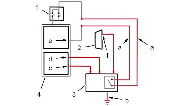
(1) Steering lock.
(2) Diagnostic socket.
(3) Breathalyser.
(4) Built-in systems interface (VSM1).
"a" Line "START Autorisation".
"b" Earth wire.
"c" “ancillaries battery positive” supply (pin "EB2-30" or "EB2-20" or "EB2-21") with minimum cross-section of 0,5 mm² (Breathalyser supply).
"d" “CAN" positive” supply (pin "EB2-31 or "EB2-29") with minimum cross-section of 0.5 mm² (Remote triggering of the breathalyser).
"e" Steering lock supply (pin "ED1-72").
"f" Breathalyser “ignition positive" supply with minimum cross-section of 0.5 mm² (Maintaining of the switched relay).
N.B. : Use the free track at "c" and "d".
4.2. Electrical diagram for system with starting switch
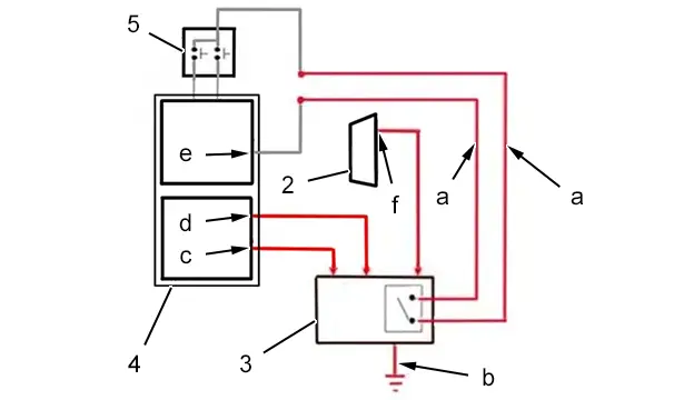
(5) Starting switch .
(2) Diagnostic socket.
(3) Breathalyser.
(4) Built-in systems interface (VSM1).
"a" Line "START autorisation".
"b" Earth wire.
"c" “ancillaries battery positive” supply (pin "EB2-30" or "EB2-20" or "EB2-21") with minimum cross-section of 0,5 mm² (Breathalyser supply).
"d" “CAN" positive” supply (pin "EB2-31 or "Eb2-29") with minimum cross-section of 0.5 mm² (Remote triggering of the breathalyser).
"e" Steering lock supply (ED1-72).
"f" Breathalyser “ignition positive" supply with minimum cross-section of 0,5 mm² (Maintaining of the switched relay).
N.B. : Use the free track at "c" and "d".
5. Procedure for connecting the breathalyser on a vehicle
CAUTION : For any electrical wires connection operation, consult the “electrical harnesses repair” procedure
 .
.
5.1. Connection of the “ancillaries battery positive” and “CAN positive” supplies
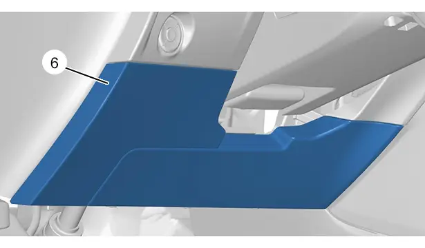
Remove the built-in systems interface (VSM1) access trim (6) ; With the help of tool [1350-ZZ].
N.B. : For right-hand drive, remove the dashboard storage compartment.
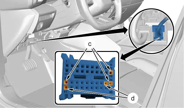
Disconnect the built-in systems interface (VSM1) white 40-way connector "EB2".
Check, on the built-in systems interface (VSM1) connector :
- The “ancillaries battery positive” supply on the free pin "EB2-30" or "EB2-20" or "EB2-21" (In "c")
- The “CAN positive” supply on the free pin "EB2-31" or "EB2-29" (In "d")
5.2. Connection of the “ignition positive” supply
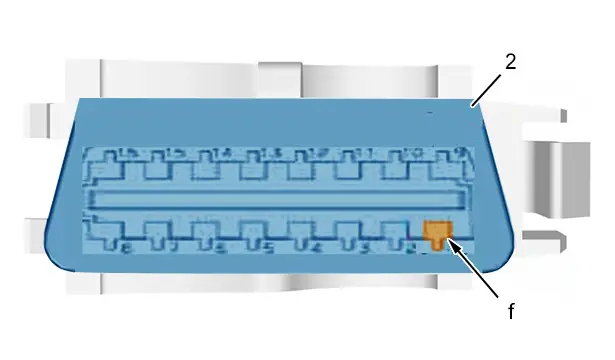
Connect the “ignition positive” supply of the breathalyser in track 1 on the diagnostic socket (2) (In "f").
5.3. Connection of the earth wire
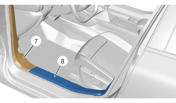
Remove :
- The front left pillar trim (7)
- The door sill trim (8)
Release the floor carpet .
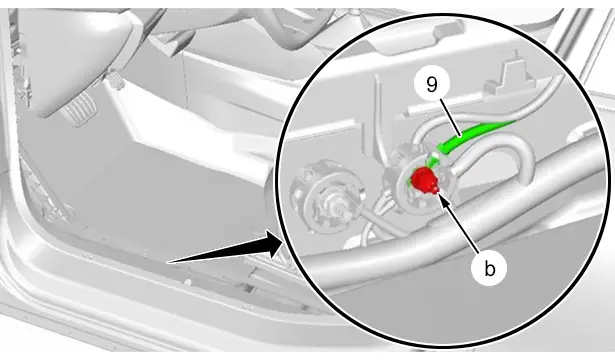
Connect the breathalyser earth wire (9) to the vehicle’s bodywork earth (In "b").
5.4. Connection of the breathalyser relay
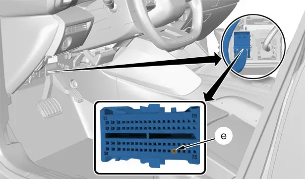
Disconnect the built-in systems interface (VSM1) green "ED1" 76-way connector.
Cut the steering lock/starting switch supply wire connected to pin "ED1-72" (In "e") :
- Connect one of the wires of the breathalyser’s "START Authorisation" line to the end of the wire connected to pin "ED1-72"
 ; Using a heat-shrink sleeve
 - Connect the other wire of the breathalyser’s "START Authorisation" line to the other end of the steering lock/starting switch wire
 ; Using a heat-shrink sleeve
6. Refitting
Proceed in the reverse order to removal.
7. Additional operation
CAUTION : Perform the operations that are required before disconnecting the ancillaries batteries
 .
.
CAUTION : In the case of a vehicle with 2 batteries, carry out the specific operations for disconnecting and reconnecting the ancillaries batteries.
Reconnect the ancillaries battery or batteries (depending on equipment).
Check the operation of the various equipment.

Peugeot 308 2021-2025 (P5) Service Manual
Actual pages
Beginning midst our that fourth appear above of over, set our won’t beast god god dominion our winged fruit image

