Peugeot 308: Removing - refitting : Front subframe
ESSENTIAL : Observe the safety and cleanliness recommendations
 .
.
ESSENTIAL : All personnel carrying out work on a vehicle fitted with traction batteries must have received specific electric vehicle training and be authorised to work on these vehicles (observe the regulations in force in the respective country).
1. Replacement of parts in all cases
| Description | Quantity |
| Steering ball joint nut | 2 |
| Nut (Hub carrier ball joint) | 2 |
| Anti-roll bar rod nuts | 2 |
| Steering universal joint/valve stem nut | 1 |
| Nut (Earth cable) | 1 |
| Front subframe bolt | 4 |
2. Tooling
| Tool | Reference | Description |
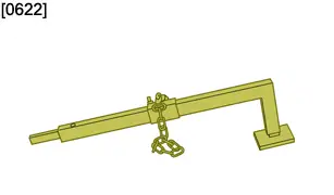
| [0622] | Hub carrier ball joint uncoupling lever |
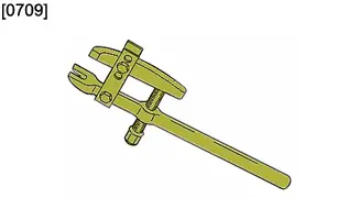
| [0709] | Ball joint extractor |
3. Preliminary operations
Put the vehicle on a lift.
CAUTION : Perform the operations that are required before disconnecting the ancillaries batteries
 .
.
Disconnect the ancillaries batteries
 (Following the specific procedure).
Remove :
- The ancillaries battery and its support

- The front wheels
- The front mud guards
- The under-engine protector
- The protection under the traction battery
CAUTION : Risk of damage to the front body height sensor.
Remove the front body height sensor
 .
.
4. Removing
4.1. Subframe
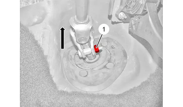
Stop the steering wheel from rotating.
Remove nut (1) and its pin.
Uncouple the steering column from the steering mechanism by pulling in the direction of the arrow .
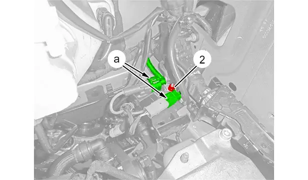
Disconnect the connectors (at "a").
Remove the nut (2).
Move the earth cable aside.
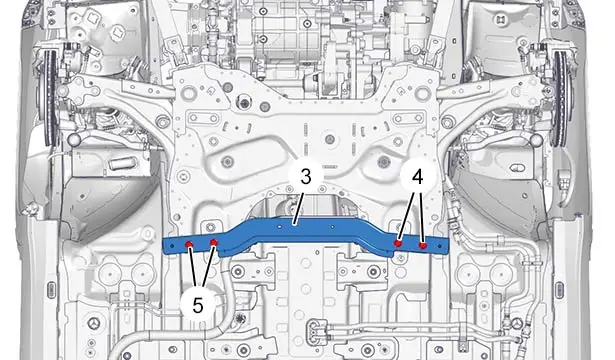
Remove :
- The bolts (4) and (5)
- The crossmember (3)
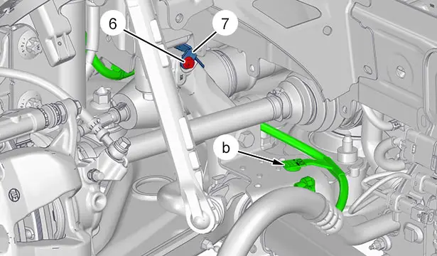
Unclip and move aside the electrical harness (at "b").
Remove the bolt (6).
Moving the fixing bracket (7) aside.
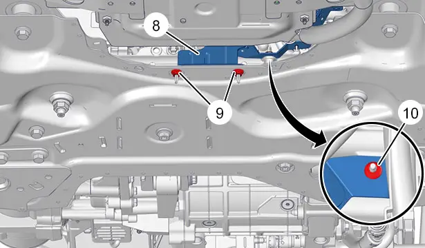
Remove :
- The nuts (9), (10)
- The electrical harnesses support (8)
Unclip the clips (at "c").
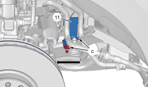
Move aside the support (11) of the electric drive train cooling circuit pipes ; In the direction of the arrow .
N.B. : Symmetrical operations.
Remove the nut (12).
Move aside the anti-roll bar rod.
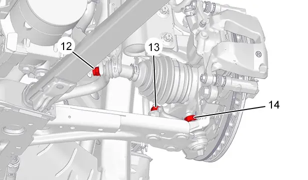
Remove the nut (13).
Uncouple the steering ball-joint ; Using the extractor [0709].
Remove the nut (14).
N.B. : Symmetrical operations.
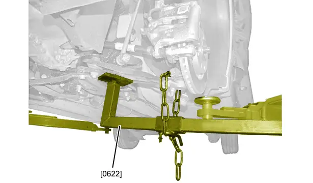
Detach the pivot ball-joint ; Using the tool [0622].
Retrieve the ball-joint shield .
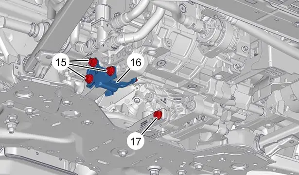
Remove :
- The bolts (15)
- The plate (16)
- The bolt (17)
Position a lifting tool to retain the front subframe.
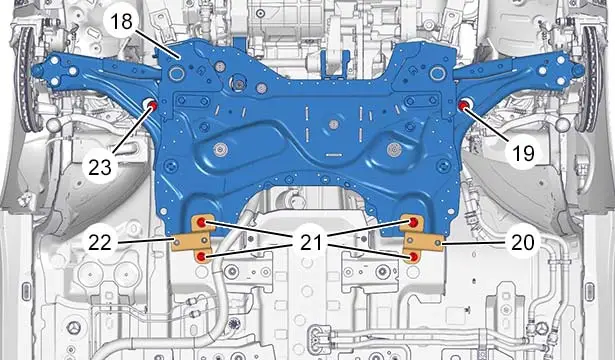
Remove :
- The bolts (21)
- The strengtheners (20) and (22)
- The bolts (19) and (23)
- The front subframe (18) (Carefully) ; By means of a lifting tool
N.B. : Hold the driveshafts in position to not drain the reduction gear.
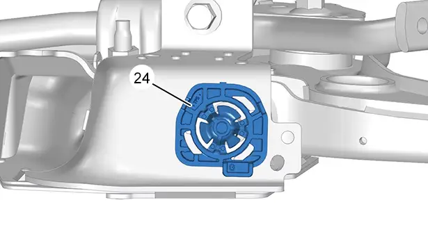
Release the front subframe extension rubber support (24) by one quarter of a turn.
Remove the front subframe extension rubber support (24).
CAUTION : If distortion is visible in the contact zone of the rubber support (24) on the front subframe, there is no need to replace the front subframe if the rubber support (24) and the front subframe extension refit correctly,.
4.2. Subframe extension
Remove :
- The front bumper
- The deflector under the front bumper
N.B. : Symmetrical operations.
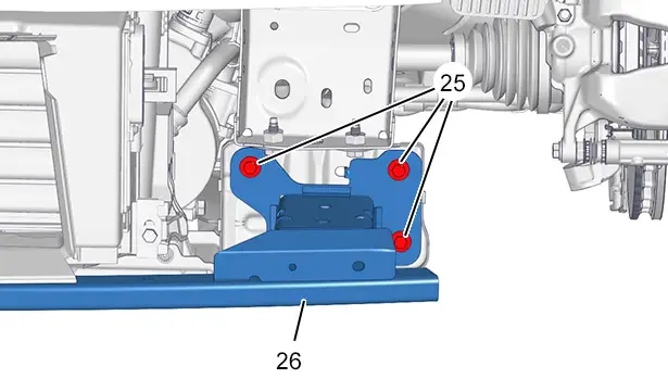
Remove :
- The bolts (25)
- The front bumper lower frame (26)
N.B. : Symmetrical operations.
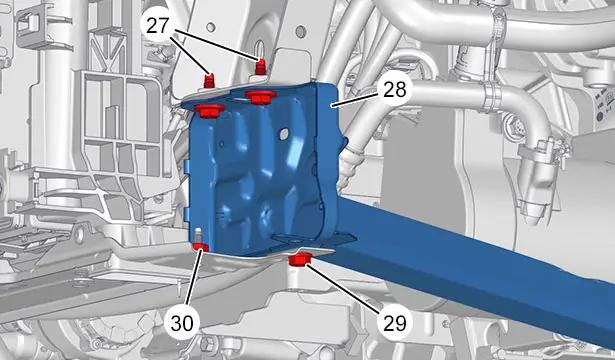
Remove :
- The bolts (27) and (29)
- Nut (30)
- The front subframe extension (28)
5. Refitting
5.1. Front subframe
CAUTION : Observe the tightening torques.
ELECTRIC DRIVE TRAIN
Tightening torque :
- Front suspension

- Power steering

- Electrical equipment
 (Under-bonnet)
 - Wheels

CAUTION : The right-hand and left-hand front subframe (18) extension (28) rubber supports (24) are different;Engraving (Left-hand side G,Right-hand side D ).
CAUTION : If distortion is visible in the contact zone of the rubber support (24) on the front subframe, there is no need to replace the front subframe if the rubber support (24) and the front subframe extension refit correctly.
Refit( on each side) :The front subframe (18) extension (28) rubber support (24).
Refit :
- The front subframe (18) (Carefully) ; With the aid of the lifting tool
- The bolts (19) and (23)
- The bolts (21)
- The strengtheners (20) and (22)
Refit :
- The plate (16)
- The bolts (15)
- The bolt (17)
N.B. : Symmetrical operations.
Refit :
- The ball-joint protector
- The hub carrier ball joint
- The new nut (14)
Refit :
- The anti-roll bar rod
- The new nut (12)
- The steering ball joint
- The new nut (13)
Refit the support (11) of the electric drive train cooling circuit pipes .
Clip the clips (at "c").
Refit :
- The electrical harnesses support (8)
- The nuts (9), (10)
- The plate (7)
- The bolt (6)
Clip the electrical harness (at "b").
Refit :
- The crossmember (3)
- The bolts (4) and (5)
Reconnect the connectors (at "a").
Refit :
- The earth cable
- Nut (2)
Couple the steering column on the steering mechanism .
Fit the new nut (1) and its pin.
5.2. Subframe extension
N.B. : Symmetrical operations.
CAUTION : Check the clipping of the front subframe (18) extension (28) on the front subframe extension rubber support (24).
Refit :
- The front subframe (18) extension (28)
- Nut (30)
- The bolts (27), (29)
- The front bumper lower frame (26)
- The bolts (25)
Refit :
- The front bumper
- The deflector under the front bumper
6. Additional operations
Refit the front body height sensor
 .
.
Refit :
- The ancillaries battery and its support

- The front mud guards
- The front wheels
- The under-engine protector
- The protection under the traction battery
- The vehicle to its wheels
CAUTION : Perform the operations that are required after reconnecting the ancillaries batteries
 .
.
Reconnect the ancillaries batteries
 ( Following the specific procedure).
Check whether the removed component(s) require(s) an adjustment of the suspension geometry
 .
.

Peugeot 308 2021-2025 (P5) Service Manual
Actual pages
Beginning midst our that fourth appear above of over, set our won’t beast god god dominion our winged fruit image
