Peugeot 308: Checking and adjusting values : Suspension geometries
ESSENTIAL : Observe the safety and cleanliness recommendations
 .
.
ESSENTIAL : All personnel carrying out work on a vehicle fitted with traction batteries must have received specific electric vehicle training and be authorised to work on these vehicles (observe the regulations in force in the respective country).
1. Tooling
| Tool | Reference | Description |
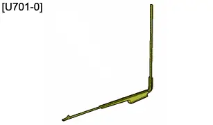
| [U701-0] | Under body height gauge |
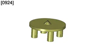
| [0924] | Wheel centre measuring table (Hub with 4 bars) |
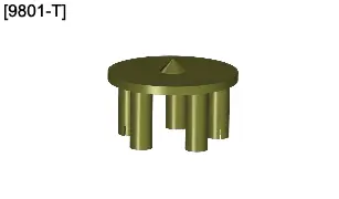
| [9801-T] | Wheel centre measuring table (Hub with 5 bars) |
2. Checking and adjusting requirements
Correct tyre pressures.
A calibration of the steering angle sensor is necessary in the following instances (depending on equipment) :
- Following replacement of the steering mechanism and after adjusting the tracking
- Following replacement of the steering column and after adjusting the tracking
- Following an after-sales operation on the tracking
CAUTION : The steering wheel is placed in the straight ahead position with the engine running.
CAUTION : If the calibration operation has not been done correctly, the fault code C1388 is recorded and the electric power steering warning lamp comes on. The functioning of the comfort strategies (stop arrival management and active recall) is altered, with customer complaints such as "noise at full lock", "steering wheel not returning to the mid-point". Too great an offset of the calibration can lead to the ESP system going into downgrade mode (Lighting of the warning lamp as well as deactivation).
3. Identification : Measuring zones - Heights of the vehicle
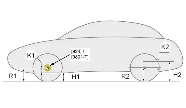
Key :
- "R1" : Front wheel radius
- "R2" : Rear wheel radius
- "H1" : Dimension between the measuring zone under the front subframe and the ground
- "H2" : Dimension between the measuring zone under the rear sidemember and the ground
- "K1" : Distance between the wheel axis and the measuring zone under the front subframe
- "K2" : Distance between the wheel axis and the measuring zone under the rear sidemember
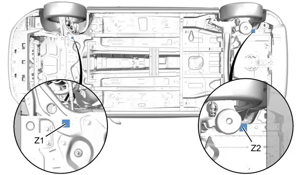
Key :
- "Z1" : Measuring zone under the front subframe
- "Z2" : Measuring zone under the rear sidemember
4. Identification of the technical solutions
| Technical solution | Body type | Driving conditions | Engine version |
| 01 | 308 (P51) / 308 SW (P52) | Standard | PHEV |
5. Geometry angles (Reminder)
| Angle | Description | Definitions |
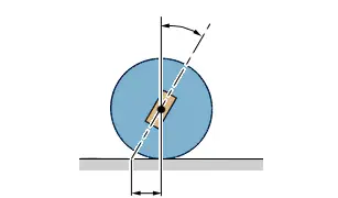
| Camber angle | Angle formed by the plane of a wheel and the vertical (Vehicle seen from the front) |
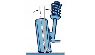
| Castor angle | Angle formed by the pivoting axis of the front wheel and the vertical (Vehicle seen from the side) |
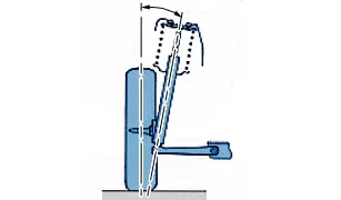
| Kingpin angle | Angle formed by the pivoting axis with the vertical, measured in the transverse plane of the vehicle (Vehicle seen from the front) |
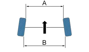
| Tracking | Difference between distance "B" and distance "A" (In the direction of the arrow : Front of the vehicle)Toe-in : "A" less than "B"Opening : "A" more than "B" |
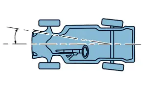
| Thrust angle | Angle formed by the thrust axis of the rear axle and the longitudinal axis of the vehicle |
6. Check of the vehicle front axle height
N.B. : This measure of the ride height permits the checking and adjustment of the tracking without placing at setting height.
Measure the radius of the front wheel "R1" ; Using the tools [0924] or [9801-T], [U701-0].
Measure the front height "H1" between the ground and the zone "Z1" ; Using the tool [U701-0].
Calculate "K1" = "R1" - "H1" for the front.
7. Checks and adjustments : Front tracking
Checking and adjustment of the front tracking is carried out by the checking of 2 different values :
- The difference in front/rear thrust angle (0° ± 0°4’)
- The tracking at the axle
N.B. : The adjustment of the difference in front and rear thrust angle ensures good stability of the vehicle’s trajectory, and the adjustment of the tracking at the axle avoids excessive tyre wear.
8. Checking and adjusting values
| "K1" | Front tracking (The axle) (± 0° 08’) |
| 91 mm | 0° 37’ |
| 101 mm | 0° 35’ |
| 111 mm | 0° 32’ |
| 121 mm | 0° 29’ |
| 131 mm | 0° 25’ |
| 141 mm | 0° 22’ |
| 151 mm | 0° 18’ |
| 161 mm (Reference) | 0° 12’ |
| 171 mm | 0° 06’ |
| 181 mm | 0° 00’ |
| 191 mm | -0° 06’ |
| 201 mm | -0° 14’ |
| 211 mm | -0° 23’ |
9. Reference height : Suspension geometries
N.B. : To carry out a full test of the geometry, place the vehicle at reference height.
9.1. Front suspension
Measure the radius of the front wheel "R1" ; Using the tools [0924] or [9801-T], [U701-0].
Calculate "H1" = "R1" - "K1" for the front.
Measure the front height "H1" between the ground and the zone "Z1" under the front subframe ; Using the tool [U701-0].
Compress the front suspension until the calculated value H1 is obtained
 .
.
The difference in height between the two sides of the front axle must be less than 10 mm.
| "K1" | Technical solution |
| 161 mm | 01 |
9.2. Rear suspension
Measure the radius of the rear wheel "R2" ; Using the tools [0924] or [9801-T], [U701-0].
Calculate "H2" = "K2" + "R2" for the rear.
Measure the rear height "H2" between the ground and the zone "Z2" under the rear sidemember ; Using the tool [U701-0].
Compress the rear suspension until the value "H2" is obtained
 .
.
The difference in height between either side of the rear axle crossmember has to be less than 10 mm.
| "K2" | Technical solution |
| -86 mm | 01 |
10. Front suspension geometry
| Tolerance | Technical solution 01 | |
| Tracking at the axle (adjustable) | ± 0° 8’ | 0° 12’ |
| Camber angle (not adjustable) | ± 0° 30’ | -0° 29’ |
| Castor (not adjustable) | ± 0° 30’ | 4° 12’ |
| Pivot angle (not adjustable) | ± 0° 30’ | 13° 00’ |
| Difference in thrust angle front/rear | 0° 4’ |
| Camber dissymmetry less than | 0° 30’ |
| Caster dissymmetry less than | 0° 30’ |
| Lower pivot angle dissymmetry at | 0° 30’ |
11. Rear axle geometry
| Tolerance | Technical solution 01 | |
| Rear thrust angle (not adjustable) | ± 0° 30’ | 0° 0’ |
| Tracking at the axle (not adjustable) | ± 0° 8’ | 0° 38’ |
| Camber angle (not adjustable) | ± 0° 30’ | -1° 45’ |
| Tolerance | |
| Camber dissymmetry less than | 0° 30’ |

Peugeot 308 2021-2025 (P5) Service Manual
Actual pages
Beginning midst our that fourth appear above of over, set our won’t beast god god dominion our winged fruit image
