Peugeot 308: Removing - refitting : Hydraulic clutch control
ESSENTIAL : Observe the safety and cleanliness recommendations
 .
.
ESSENTIAL : Whenever you send any components of the hydraulic clutch control to the guarantee return centre, plug the openings of the components removed, so as to aid the analysis (Use the plugs that are on the new components) . There are 2 systems for linking the clutch pedal transmitter: cylindrical link ; ball-joint link.
N.B. : Use the products recommended by the manufacturer
 .
.
Draining :
- Clutch control circuit

- Hydraulic control master cylinder with cylindrical link on the clutch pedal

- Hydraulic control master cylinder with ball-joint link on the clutch pedal

- Hydraulic clutch control slave cylinder
 (Bleed system with clip)
 - Hydraulic clutch control slave cylinder
 (Screw bleed system)
 - Fitting with hydraulic stop

- Hydraulic clutch pipe

1. Tooling
| Tool | Reference | Description |
| [0350] | Repair kit for gearbox |
| [0350-C][DT-6202-B] | Gear control locking tool |
2. Preliminary operations
Place the vehicle on a 2-post lift.
CAUTION : Perform the operations that are required prior to a disconnection of the ancillaries battery
 .
.
Disconnect the ancillaries battery.
Remove parts as necessary for removing the component(s) of the hydraulic clutch control.
3. Drain : Clutch control circuit
CAUTION : Mark the level of brake fluid in the reservoir before carrying out the operation.
There is more than one bleed system :
- Single-clip bleed system
- Double-clip bleed system
- Screw bleed system
3.1. Single-clip bleed system
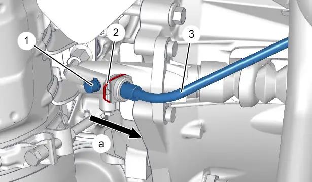
CAUTION : When reconnecting and disconnecting it, handle the hydraulic pipe (3) keeping it straight and do not lever it to prevent any break.
CAUTION : The use of pliers and screwdrivers to act as a lever on the clip is prohibited, risk of loss of the clutch function.
Remove the protection cap (1) from the bleed orifice .
Store the protective cap (1) in a clean place.
Couple a transparent pipe onto the bleed orifice .
CAUTION : The end of the transparent pipe must be submerged into the brake fluid.
Remove the brake fluid reservoir cap .
N.B. : The press on the clip (2) may require considerable force.
Push the hydraulic pipe (3) (In the opposite direction to the arrow "a").
Press on the clip (2) and pull on the hydraulic pipe (3) over approximately 5 mm to free the bleed aperture (In the direction of the arrow "a").
Allow the brake fluid to flow out by gravity.
Push in the hydraulic pipe (3) to close the bleed orifice (In the opposite direction to the arrow "a").
Refit the brake fluid reservoir cap .
Uncouple the transparent pipe.
Refit the protection cap (1) on the bleed orifice .
3.2. Double-clip bleed system
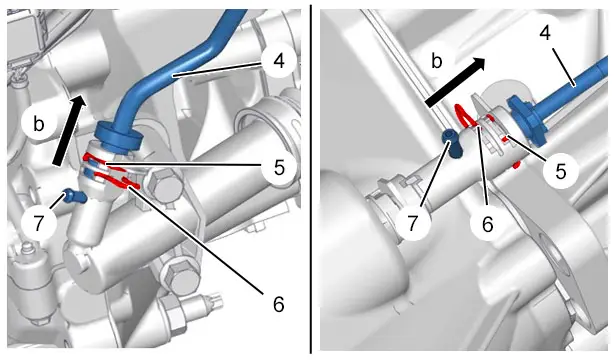
CAUTION : When reconnecting and disconnecting it, handle the hydraulic pipe (4) keeping it straight and do not lever it to prevent any break.
Remove the protection cap (1) from the bleed orifice (7).
Store the protection cap in a clean place.
Couple a transparent pipe (1) onto the bleed orifice (7).
CAUTION : The end of the transparent pipe must be submerged into the brake fluid.
Re-clip the clip (5).
CAUTION : The clip (5) must always remain clipped in position on the hydraulic clutch slave cylinder during the bleed.
Unclip the clip (6).
Pull on the hydraulic pipe (4) to free the bleed orifice (7) (In the direction of the arrow "b").
Allow the brake fluid to flow out by gravity.
Re-clip the clip (6).
Push in the hydraulic pipe (4) to close the bleed orifice (7) (In the opposite direction to the arrow "b").
Unclip the clip (5) (without removing it).
Uncouple the transparent pipe.
Refit the protection cap on the bleed aperture (7).
3.3. Screw bleed system (Quarter turn system)
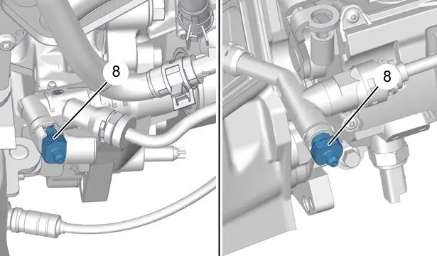
Remove the bleed screw (8) protection cap.
Store the protection cap in a clean place.
Couple a transparent tube on the bleed screw (8).
CAUTION : The end of the transparent pipe must be submerged into the brake fluid.
Rotate the bleed screw (8) a quarter turn (clockwise).
Allow the brake fluid to flow out by gravity.
Close the bleed screw (8) (anti clockwise).
Uncouple the transparent pipe.
Refit the protection cap on the bleed screw (8).
3.4. Screw bleed system (6-sided screw system)
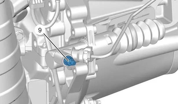
Remove the bleed screw (9) protection cap.
Store the protection cap in a clean place.
Couple a transparent tube on the bleed screw (9).
CAUTION : The end of the transparent pipe must be submerged into the brake fluid.
Turn the bleed screw (9) (anti clockwise).
Allow the brake fluid to flow out by gravity.
Close the bleed screw (9) (clockwise).
Uncouple the transparent pipe.
Refit the protection cap on the bleed screw (9).
4. Hydraulic control master cylinder with cylindrical link on the clutch pedal
4.1. Removing
CAUTION : When coupling and uncoupling, keep the hydraulic pipe in its axis and do not use it as a lever, so as to avoid any rupturing.
CAUTION : Do not break the lugs on the head of the rod on the hydraulic clutch control master cylinder.
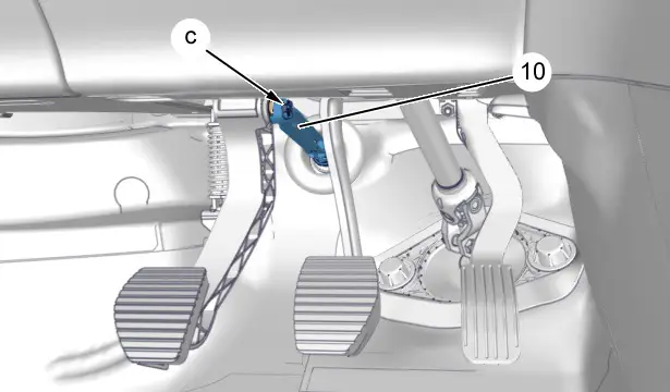
Unclip the rod (10) from the hydraulic clutch master cylinder (In "c").

CAUTION : Prepare for the flow of brake fluid ; Use a cloth.
Uncouple the supply pipe (11) (In "d").
Plug the opening of the brake fluid reservoir (In "d") ;With a clean cap.
Unclip the clip (12).
Uncouple the hydraulic pipe (13) (In "e").
Unlock the hydraulic clutch control master cylinder (14) (Rotate an eighth turn clockwise).
Remove the hydraulic clutch control master cylinder (14).
4.2. Refitting
CAUTION : When coupling it, handle the hydraulic pipe (13) keeping it straight and not levering it to prevent any break.
Lightly lubricate the connection between the rod (10) of the hydraulic clutch master cylinder (14) and the pedal bracket ; Using grease index "G7"
 .
.
Refit the hydraulic clutch control master cylinder (14).
Lock the hydraulic clutch control master cylinder (14) (Rotate an eighth turn anti-clockwise).
Re-clip the clip (12).
Couple up :
- The hydraulic pipe (13) (In "e")
- The supply pipe (11) (In "d")
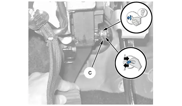
Clip the rod (10) of the hydraulic clutch master cylinder (14) (In "c").
Check the clipping of the hydraulic clutch control master cylinder rod (10) (In "c") (Pull-push).
5. Hydraulic control master cylinder with ball-joint link on the clutch pedal
5.1. Removing : Pedal bracket end
N.B. : First assembly (Pedal bracket).
CAUTION : When reconnecting and disconnecting it, handle the hydraulic pipe (13) keeping it straight and do not lever it to prevent any break.
CAUTION : Do not break the lugs on the head of the rod on the hydraulic clutch control master cylinder.
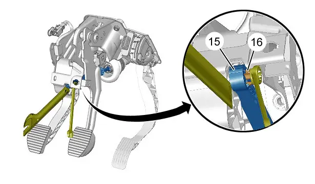
Carry out the following operations simultaneously :
- Pinch together the lugs of the locking clip (16) ; Using a ring spanner no. 10
- Move aside the rod (15) from the pedal gear ; Using a plastic pallet
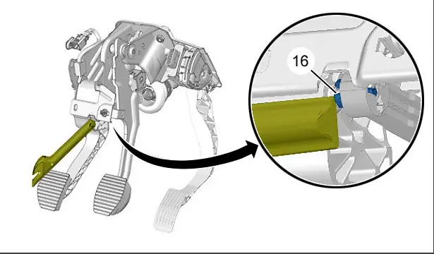
Release the locking clip (16) from the pedal bracket ; Using a plastic pallet.
N.B. : Second assembly (Pedal bracket).
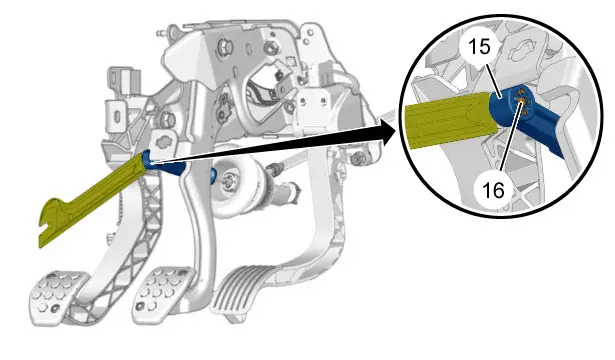
Press on the locking clip (16).
Disconnect the rod (15) of the hydraulic clutch control master cylinder from the pedal bracket ; Using a plastic pallet.
N.B. : Third assembly (Pedal bracket).
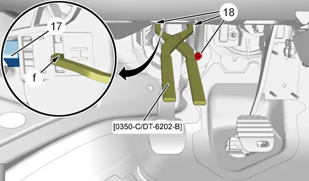
Unclip the hydraulic clutch control master cylinder (17) ; Using the tool [0350-C / DT-6202-B] (In "f").
Remove the nuts (18).
Move the hydraulic clutch control master cylinder (17) rod away from the pedal bracket.
Remove the clutch pedal support and hydraulic clutch control master cylinder assembly .
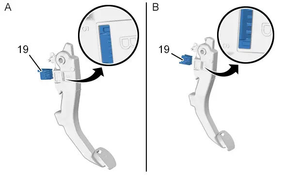
CAUTION : During removal ; Mark the direction of fitting of the clip (19).
Assembly "A" : Clip in position 5.
Assembly "B" : Clip in position 6.
| Clip position | Travel | Vehicle | Associated engines / Engine - gearbox assembly |
| 5 | Travel 23.5 | 308 (P51) | DV5R/ML6 |
| 5 | Travel 25 | TRAVELLER (K0) - EXPERT IV (K0), (KR) | DV6D-FD / BE |
| 6 | Travel 23.5 | DV6FC/ML6C | |
| 6 | Travel 23.5 | DW10F/ML6C | |
| 5 | Travel 26 | 308 (T9) | DV6C/MCM |
| 5 | Travel 26 | EB2-EB2F/BE | |
| 5 | Travel 25 | EP6CDTX/MCM | |
| 5 | Travel 25 | DV5R/ML6 | |
| 5 | Travel 25 | DV6FD-FD-FE/BE | |
| 6 | Travel 25 | DV6FC/ML + EB2DT/DTS | |
| 6 | Travel 23.5 | DW10FD/ML6C Ra45 | |
| 5 | Travel 23.5 | EC5-EP6C/BE-EP6CM/BE | |
| EP6FADTR/BVM-MC | |||
| 5 | Travel 25 | 3008 (P84) - 5008 (P87) | DV6D-FD-FE/BE |
| 5 | Travel 23.5 | DV5R/ML6 | |
| 6 | Travel 23.5 | DV5R/ML6 | |
| 6 | Travel 23.5 | DV6FC/ML6C-EB2DT/BE-EB2DTSM/MCM | |
| 6 | Travel 23.5 | DW10FD/ML6C Ra45 |
5.2. Removing : Hydraulic clutch control master cylinder end
N.B. : First assembly (Master cylinder).
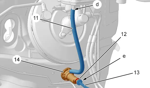
N.B. : Prepare for the flow of brake fluid ; Use a cloth.
Uncouple the supply pipe (11) (In "d").
Plug the opening of the brake fluid reservoir (In "d") ; With a clean cap.
Unclip the clip (12).
Uncouple the hydraulic pipe (13) (In "e").
Unlock the hydraulic clutch control master cylinder (14) (Rotate an eighth turn clockwise).
Remove the hydraulic clutch control master cylinder (14).
N.B. : Second assembly (Master cylinder).
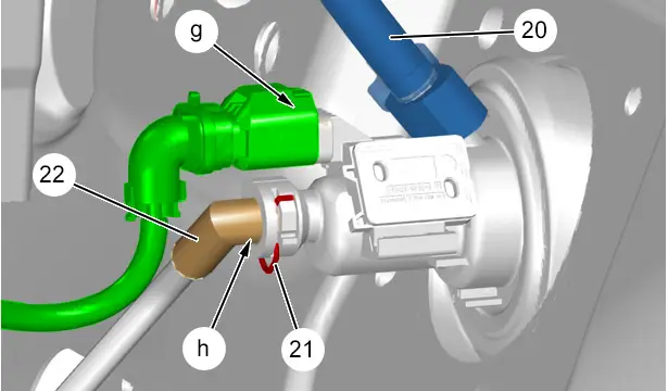
Disconnect the connector (at "g").
Uncouple the supply pipe (20) from the brake fluid reservoir.
Plug the opening of the brake fluid reservoir ; With a clean cap.
Unclip the clip (21).
Uncouple the hydraulic pipe (22) (In "h").
Unlock the hydraulic clutch control master cylinder (17) (Rotate an eighth turn clockwise).
Remove the hydraulic clutch control master cylinder (17).
5.3. Refitting : Hydraulic clutch control master cylinder end
CAUTION : When coupling up, keep the hydraulic pipe in its axis and do not use it as a lever, so as to avoid any rupturing.
N.B. : First assembly (Master cylinder).
Refit the hydraulic clutch control master cylinder (14).
Lock the hydraulic clutch control master cylinder (14) (Rotate an eighth turn anti-clockwise).
Clamp the clip (12).
Couple up :
- The hydraulic pipe (13) (In "e")
- The supply pipe (11) (In "d")
N.B. : Second assembly (Master cylinder).
Refit the hydraulic clutch control master cylinder (17) on the clutch pedal support.
Couple up :
- The hydraulic pipe (22) (In "h")
- The supply pipe (20)
Refit the clutch pedal support and hydraulic clutch control master cylinder assembly .
Clamp the clip (21).
Reconnect the connector (In "g").
5.4. Refitting : Pedal bracket end
N.B. : First assembly (Pedal bracket).
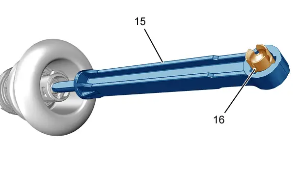
CAUTION : Check that the master cylinder locking clip (16) of the new hydraulic clutch control is in the position shown above.
Reclip :
- The locking clip (16) on the pedal bracket
- The rod (15) of the hydraulic clutch control master cylinder on the locking clip (16)
N.B. : Second assembly (Pedal bracket).

CAUTION : Check that the master cylinder locking clip (16) of the new hydraulic clutch control is in the position shown above.
Reclip :
- The locking clip (16) on the pedal bracket
- The rod (15) of the hydraulic clutch control master cylinder on the locking clip (16)
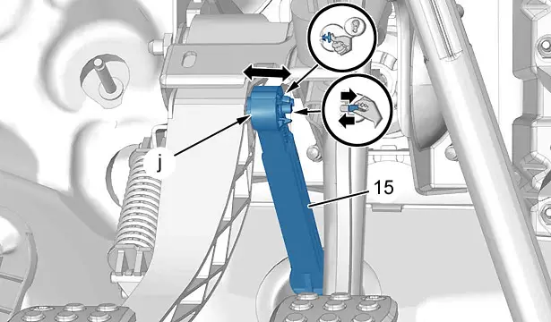
Check the clipping of the hydraulic clutch control master cylinder rod (15) (In "j") (Pull-push).
N.B. : Third assembly (Pedal bracket).
Refit the nuts (18).
Re-clip the clip (19).
6. Hydraulic clutch control slave cylinder (Bleed system with clip)
6.1. Removing the single-clip bleed system
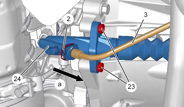
CAUTION : When reconnecting and disconnecting it, handle the hydraulic pipe (3) keeping it straight and do not lever it to prevent any break.
N.B. : Prepare for the flow of brake fluid ; Use a cloth.
Push the hydraulic pipe (3) (In the opposite direction to the arrow "a").
Press on the clip (2) and pull on the hydraulic pipe (3) over approximately 5 mm to free the bleed aperture (In the direction of the arrow "a").
Allow the brake fluid to flow out by gravity.
Press on the clip (2) and uncouple the hydraulic pipe (3) (In the direction of the arrow "a").
Remove :
- The bolts (23)
- The hydraulic clutch control slave cylinder (24)
6.2. Removing the double-clip bleed system
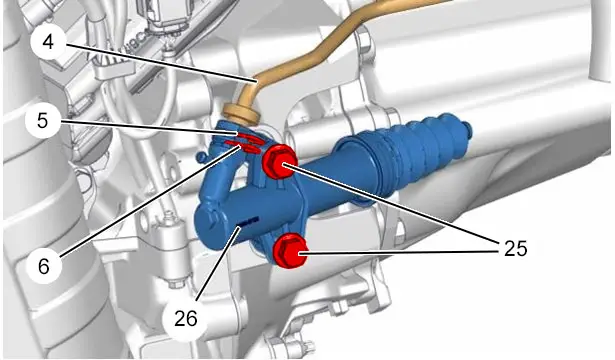
CAUTION : When reconnecting and disconnecting it, handle the hydraulic pipe (4) keeping it straight and do not lever it to prevent any break.
N.B. : Prepare for the flow of brake fluid ; Use a cloth.
Unclip the clips (5), (6) (without removal).
Uncouple the hydraulic pipe (4).
Remove :
- The bolts (25)
- The hydraulic clutch control slave cylinder (26)
6.3. Refitting the single-clip bleed system
CAUTION : Observe the tightening torques.
CAUTION : When coupling it, handle the hydraulic pipe (3) keeping it straight and not levering it to prevent any break.
Lightly lubricate the connection between the rod of the hydraulic clutch slave cylinder (24) and the clutch fork ; Using grease index "G12".
Refit :
- The hydraulic clutch control slave cylinder (24)
- The (new) bolts (23)
Connect the hydraulic pipe (3).
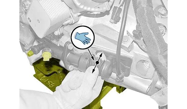
Check the positioning of the hydraulic clutch control slave cylinder rod in the clutch fork.
6.4. Refitting the double-clip bleed system
CAUTION : Observe the tightening torques.
CAUTION : When coupling it, handle the hydraulic pipe (4) keeping it straight and not levering it to prevent any break.
Lightly lubricate the connection between the rod of the hydraulic clutch slave cylinder (26) and the clutch fork ; Using grease index "G12".
Refit :
- The hydraulic clutch control slave cylinder (26)
- The (new) bolts (25)
Refit the clips (5), (6).
Connect the hydraulic pipe (4).
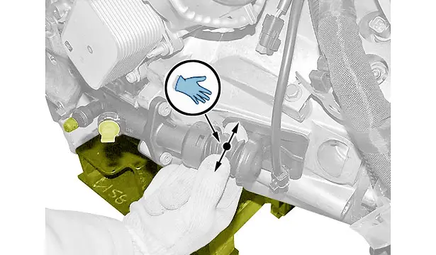
Check the positioning of the hydraulic clutch control slave cylinder rod in the clutch fork.
7. Hydraulic clutch control slave cylinder (Screw bleed system)
7.1. Removing
CAUTION : When coupling and uncoupling, keep the hydraulic pipe in its axis and do not use it as a lever, so as to avoid any rupturing.

N.B. : Prepare for the flow of brake fluid ; Use a cloth.
Unclip the clip (27) (without removal).
Uncouple the hydraulic pipe (28) (In "k").
Remove :
- The bolts (29)
- The hydraulic clutch control slave cylinder (30)
7.2. Refitting
CAUTION : Observe the tightening torques.
CAUTION : When coupling it, handle the hydraulic pipe (28) keeping it straight and not levering it to prevent any break.
Lightly lubricate the connection between the rod of the hydraulic clutch slave cylinder (30) and the clutch fork ; Using grease index "G12".
Refit :
- The hydraulic clutch control slave cylinder (30)
- The (new) bolts (29)
Re-clip the clip (27).
Connect the hydraulic pipe (28) (In "k").
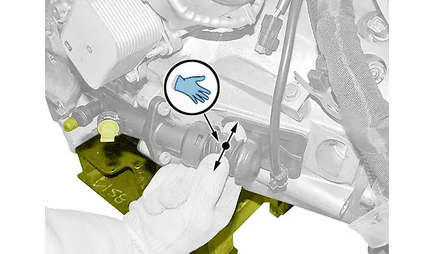
Check the positioning of the hydraulic clutch control slave cylinder rod in the clutch fork.
8. Fitting with hydraulic stop
8.1. Removing : Screw bleed system (Quarter turn system)
CAUTION : When coupling and uncoupling, keep the hydraulic pipe in its axis and do not use it as a lever, so as to avoid any rupturing.

N.B. : Prepare for the flow of brake fluid ; Use a cloth.
Unclip the clip (32) (without removal).
Uncouple the hydraulic pipe (33) (In "l").
Remove :
- The clip (31)
- The bleed union (34)
- The gearbox
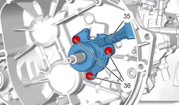
Remove :
- The bolts (36)
- The hydraulic stop (35)
8.2. Refitting : Screw bleed system (Quarter turn system)
CAUTION : Observe the tightening torques.
CAUTION : When coupling it, handle the hydraulic pipe (28) keeping it straight and not levering it to prevent any break.
Refit :
- The hydraulic stop (35)
- The bolts (36)
- The gearbox
- The bleed union (34)
- The clip (31)
Re-clip the clip (32).
Connect the hydraulic pipe (33) (In "l").
8.3. Removing : Double-clip bleed system
CAUTION : When coupling and uncoupling, keep the hydraulic pipe in its axis and do not use it as a lever, so as to avoid any rupturing.
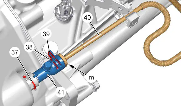
N.B. : Prepare for the flow of brake fluid ; Use a cloth.
Unclip the clips (38), (39) (without removal).
Uncouple the hydraulic pipe (40) (In "m").
Unclip the clip (37) (without removal).
Remove :
- The bleed union (41)
- The gearbox
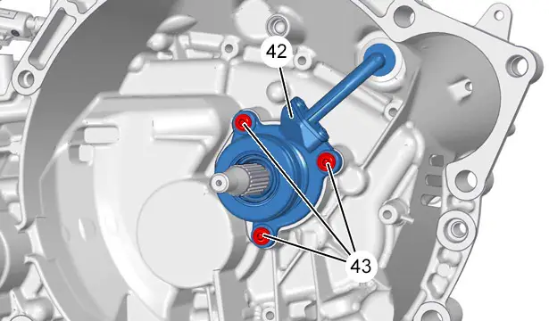
Remove :
- The bolts (43)
- The hydraulic stop (42)
8.4. Refitting : Double-clip bleed system
CAUTION : Observe the tightening torques.
CAUTION : When coupling it, handle the hydraulic pipe (40) keeping it straight and not levering it to prevent any break.
Refit :
- The hydraulic stop (42)
- The bolts (43)
- The gearbox
- The bleed union (41)
Re-clip the clip (37).
Connect the hydraulic pipe (40) (In "m").
Refit the clips (38), (39).
9. Hydraulic clutch pipe
CAUTION : When coupling and uncoupling, keep the hydraulic pipe in its axis and do not use it as a lever, so as to avoid any rupturing.
N.B. : There are 3 connection systems between the hydraulic pipe (13) and the hydraulic clutch slave cylinder (14).
9.1. Removing : Hydraulic clutch control master cylinder end
N.B. : First assembly (Master cylinder).
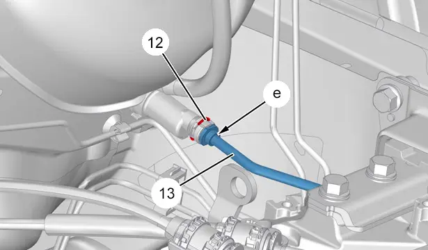
Unclip the clip (12) (without removal).
Uncouple the hydraulic pipe (13) (In "e").
N.B. : Second assembly (Master cylinder).
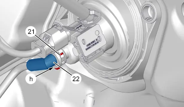
Unclip the clip (21).
Uncouple the hydraulic pipe (22) (In "h").
9.2. Removing : Hydraulic clutch control slave cylinder side (Single-clip bleed system)
CAUTION : When reconnecting and disconnecting it, handle the hydraulic pipe (3) keeping it straight and do not lever it to prevent any break.
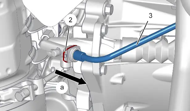
N.B. : Prepare for the flow of brake fluid ; Use a cloth.
Push the hydraulic pipe (3) (In the opposite direction to the arrow "a").
Press on the clip (2) and pull on the hydraulic pipe (3) over approximately 5 mm to free the bleed aperture (In the direction of the arrow "a").
Allow the brake fluid to flow out by gravity.
Press on the clip (2) and uncouple the hydraulic pipe (3) (In the direction of the arrow "a").
9.3. Removing : Hydraulic clutch control slave cylinder side (Double-clip bleed system)
CAUTION : When reconnecting and disconnecting it, handle the hydraulic pipe (4) keeping it straight and do not lever it to prevent any break.
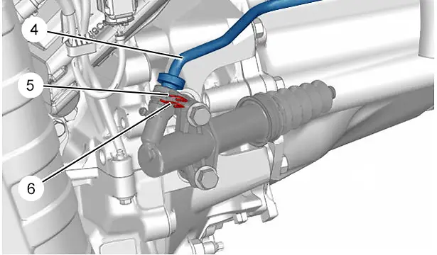
N.B. : Prepare for the flow of brake fluid ; Use a cloth.
Unclip the clips (5), (6) (without removal).
Uncouple the hydraulic pipe (4).
9.4. Removing : Hydraulic clutch control slave cylinder side (Screw bleed system)
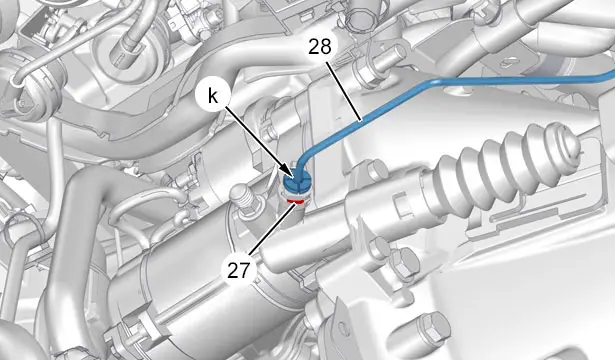
N.B. : Prepare for the flow of brake fluid ; Use a cloth.
Unclip the clip (27) (without removal).
Uncouple the hydraulic pipe (28) (In "k").
9.5. Removing : On the bleed union for hydraulic stop (35) (Quarter turn system)
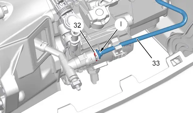
N.B. : Prepare for the flow of brake fluid ; Use a cloth.
Unclip the clip (32) (without removal).
Uncouple the hydraulic pipe (33) (In "l").
9.6. Removing : Hydraulic stop bleed union end (Double-clip bleed system)
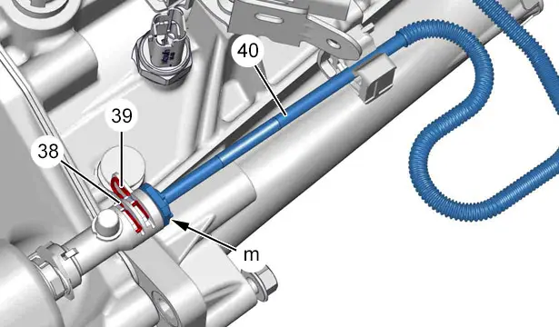
N.B. : Prepare for the flow of brake fluid ; Use a cloth.
Unclip the clips (38), (39) (without removal).
Uncouple the hydraulic pipe (40) (In "m").
9.7. Refitting
CAUTION : When coupling up, keep the hydraulic pipe in its axis and do not use it as a lever, so as to avoid any rupturing.
9.8. Refitting : On the bleed union for hydraulic stop (42) (Double-clip bleed system)
Connect the hydraulic pipe (40) (In "m").
Re-clip the clip (38).
9.9. Refitting : On the bleed union for hydraulic stop (35) (Quarter turn system)
Connect the hydraulic pipe (33) (In "l").
Re-clip the clip (32).
9.10. Refitting : Hydraulic clutch control slave cylinder (30) side (Screw bleed system)
Connect the hydraulic pipe (28) (In "k").
Re-clip the clip (27).
9.11. Refitting : Hydraulic clutch control slave cylinder (26) side (Double-clip bleed system)
Connect the hydraulic pipe (4).
Re-clip the clip (6).
9.12. Refitting : Hydraulic clutch control slave cylinder (24) side (Single-clip bleed system)
Connect the hydraulic pipe (3).
9.13. Refitting : Hydraulic clutch control master cylinder end ; Second assembly
Connect the hydraulic pipe (22) (In "h").
Re-clip the clip (21).
9.14. Refitting : Hydraulic clutch control master cylinder end ; First assembly
Connect the hydraulic pipe (13) (In "e").
Re-clip the clip (12).
10. Additional operations
Bleed the clutch hydraulic control.
Refit the parts that were removed for removal of the component(s) of the hydraulic clutch control.
RefitThe vehicle to its wheels.
CAUTION : Perform the operations that are required after reconnecting the ancillaries battery
 .
.
Reconnect the ancillaries battery.
CAUTION : Check that the bleed opening is correctly closed by operating the clutch pedal several times and checking that there are no leaks or seeping (risk of vehicle fire in the event of a leak).

Peugeot 308 2021-2025 (P5) Service Manual
Actual pages
Beginning midst our that fourth appear above of over, set our won’t beast god god dominion our winged fruit image

