Peugeot 308: Refitting : Engine bottom
ESSENTIAL : Observe the safety and cleanliness recommendations
 .
.
ESSENTIAL : All personnel carrying out work on a vehicle fitted with traction batteries must have received specific electric vehicle training and be authorised to work on these vehicles (observe the regulations in force in the respective country).
1. Tooling
| Tool | Reference | Description |
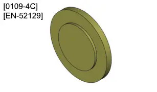
| [0109-4C][EN-52129] | Conrod half shell centring tool (39 and 45 mm diameter) |
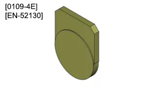
| [0109-4E][EN-52130] | Crankshaft half-shell centring tool for EB2 engine |
2. Preparation of the con rods
CAUTION : Observe the tightening torques
 .
.
CAUTION : Do not switch the line shells and big end shells of the EB2L engines (The diameter of the bearings is identical, but the thickness and part number of the shells are different).
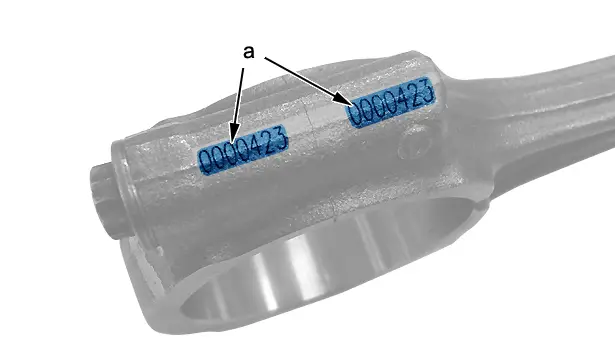
CAUTION : Identify the fitting direction of the big end bearing caps on the con rod (paint marks at removal or marking (at "a") on new con rod).
3. Classification of the big end lower half-shells
Pair the big end lower half-shells in accordance with the marks on the crankshaft and on the big end cap
 .
.
3.1. EB2L engine types
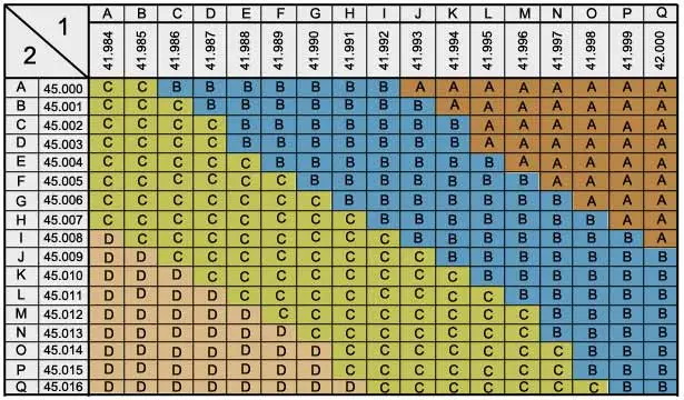
(1) Crank pin diameter.
(2) Big end bore.
| Identification (Double colour marking) | Nominal dimension |
| Class "A" (Brown in colour) | 1,482 ± 0,003 mm |
| Class "B" (Coloured blue) | 1,489 ± 0,003 mm |
| Class "C" (Green) | 1,496 ± 0,003 mm |
| Class "D" (Yellow) | 1,503 ± 0,003 mm |
3.2. Example
Characters read on the crankshaft : JHH.
Character read on the con rod of cylinder number 1 : L.
The lower half-shell to be fitted for cylinder number 1 is class "C" (Green).
Proceed in the same way for the 2 other assemblies.
4. Connecting rod half shells
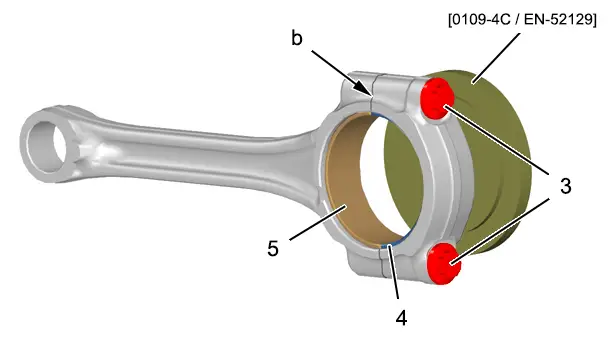
Oil and refit the big end half shell bearings (4), (5) onto the con rod and the big end bearing cap.
Manually pre-tighten the big end cap bolts (3), without forcing.
Centre and align the big end half shells (4), (5) (at "b") ; Using the tool [0109-4C / EN-52129].
N.B. : The tool [0109-4C / EN-52129] is reversible ; Use the face of the tool [0109-4C / EN-52129] corresponding to the diameter of the big end.
Remove :
- The bolts (3)
- The conrod cap
Mark the big end cap.
Repeat the operation on the 2 other assemblies.
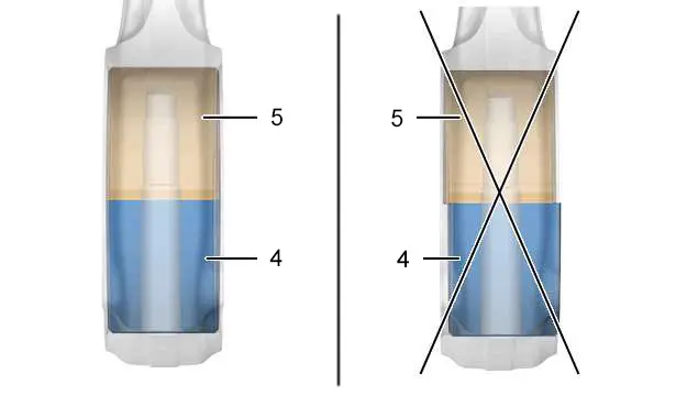
CAUTION : The big end half shell bearings (4), (5) must be aligned and centred on the con rod.
5. Connecting rod/piston assemblies
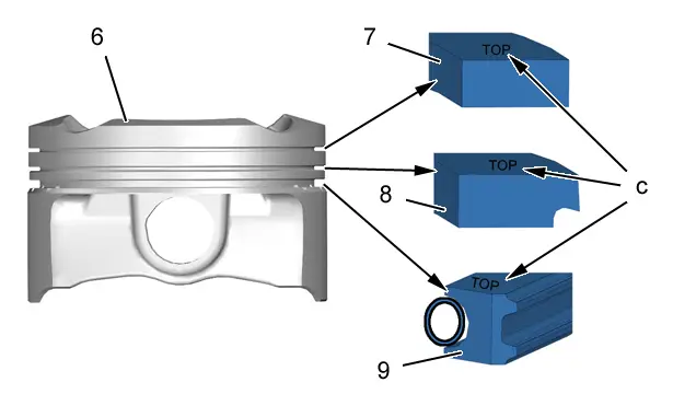
CAUTION : Observe the direction of fitting of the piston rings (7), (8), (9) (Mark "TOP" (at "c") at the top).
Fit the 3 piston rings (7), (8), (9) on the piston (6) ; Using the piston ring pliers and observing the following order of fitting :
- The scraper ring (9) in the lower groove
- The compression ring (8) in the central groove
- The top ring (7) in the upper groove
CAUTION : The scraper ring (9) must be arranged at 180° from the spring cut.
N.B. : Check the rotation of the piston rings (7), (8), (9) in the grooves before inserting the pistons in the liners ; No point of resistance on rotation should be felt.
CAUTION : Position the rings by thirds so that the gaps in them are at 120°.
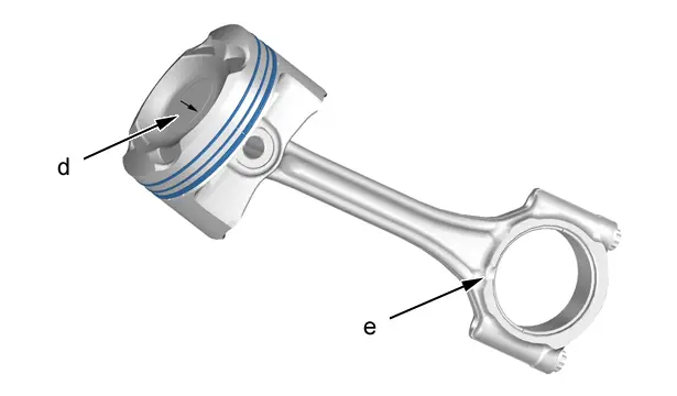
Check the orientation of the piston and of the con rod :
- Arrow (at "d") directed to the timing side
- Lug (at "e") directed to the inlet side
CAUTION : Depending on the type of rod, the lug (at "e") may be on the timing side or the engine flywheel side, but in all cases the lug must be directed to the inlet side.
CAUTION : Oil the side faces of the pistons (6) and the piston rings (7), (8), (9) with engine oil before insertion into the cylinder block.
Oil the pistons fitting tool and push evenly on the piston top until it is inserted fully in the liner.
CAUTION : If there is a tight point, do not force it; withdraw the assembly, check the pistons and the grooves, then repeat the operation.
CAUTION : In the case of scratching in the liner, remove the assembly again and check that none of the piston rings (7), (8), (9) are broken.
6. Crankshaft half shells
6.1. Upper half-shells on cylinder block
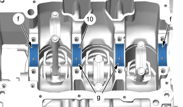
CAUTION : The crankshaft bearing half-shells (10) numbered 1 and 4 are partially grooved (at "f").
CAUTION : The crankshaft bearing half-shells (10) numbered 2 and 3 are partially grooved (at "g").
Oil and refit the crankshaft bearings upper half-shells (10).
| Identification (Single colour marking) | Nominal dimension of upper thermal bearings EB2L | Bearing number |
| Black colour | 1,798 mm | 1, 4 (smooth) |
| Not applicable | 1,798 mm | 2, 3 (grooved) |
| Identification (Single colour marking) | Nominal dimension of upper bearings EB2L MHEV | Bearing number |
| Black colour | 1,795 mm | 1 (smooth) |
| Not applicable | 1,795 mm | 2, 3 (grooved) |
| Red | 1,795 mm | 4 (smooth) |
CAUTION : The upper crankshaft bearings in internal combustion engines EB2L and EB2L MHEV are different and must not be reversed.
N.B. : Only the upper bearing n°4 in EB2L MHEV engines contains polymer for faster lubrication.
6.2. Classification of the crankshaft lower half-shells
Pair the crankshaft lower half-shells according to the marks on the crankshaft and on the cylinder block
 .
.
6.3. EB2L engine types
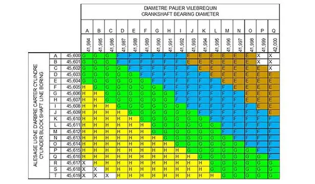
| Identification (Single colour marking) | Nominal dimension of lower thermal bearings EB2L 100% | Nominal dimension of lower bearings EB2L MHEV | Bearing number |
| Class "E" (brown) | 1,789 mm | 1,786 mm | 1, 2, 3, 4 |
| Class "F" (blue) | 1,795 mm | 1,792 mm | 1, 2, 3, 4 |
| Class "G" (green) | 1,802 mm | 1,798 mm | 1, 2, 3, 4 |
| Class "H" (yellow) | 1,807 mm | 1,804 mm | 1, 2, 3, 4 |
CAUTION : The lower crankshaft bearings in internal combustion engines EB2L and EB2L MHEV are different and must not be reversed.
N.B. : Only the lower bearing in EB2L MHEV engines contains polymer for faster lubrication.
6.4. Example
For bearing no. 1 (engine flywheel side).
Characters read on the crankshaft : OLMM.
Characters on the cylinder block : KLKJ.
The smooth lower half-shell to be fitted is class "B".
6.5. Positioning of the crankshaft bearing half-shells
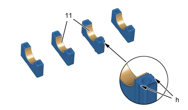
Oil and refit the crankshaft bearings lower half-shells (11).
CAUTION : The lower half-shells (11) are smooth and classed by thickness.
CAUTION : Bearing number 2 is wider to support the crankshaft end float shims (at "h").
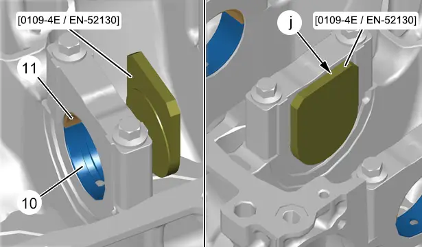
Refit the crankshaft bearings, without tightening them.
Align the lower (11) and upper (10) shells ; Using the tool [0109-4E / EN-52130] ; Place the centring tool [0109-4E/EN-52130] flush against the crankshaft bearing (at "j").
Repeat the operation on the other 3 bearings.
Remove the crankshaft bearings .
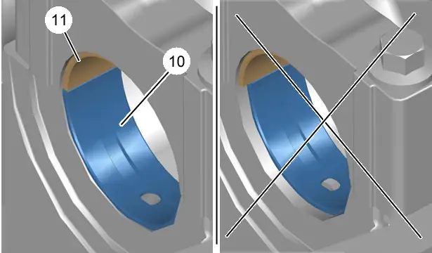
CAUTION : The crankshaft half-shells (11), (10) must be aligned and centred in relation to the crankshaft bearing.
7. Crankshaft
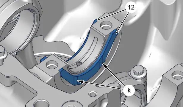
Grease on each side and refit the two crankshaft end float half-flanges (12) on bearing number 2.
CAUTION : Observe the direction of fitting of the two crankshaft end float half-flanges (12) ; Grooves (at "k"), crankshaft side.
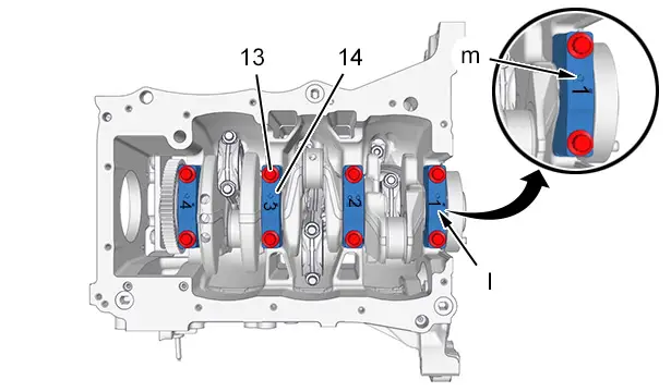
CAUTION : Observe the direction of fitting of the crankshaft bearing caps (14).
The crankshaft main bearing caps (14) are numbered from 1 to 4 (at "l") (Cylinder number 1 is located on the flywheel side).
The concave part of each crankshaft bearing (14) (at "m") must be directed to the exhaust side.
Refit :
- The crankshaft
- The main bearing caps (14)
- The bolts (13)
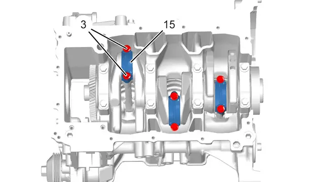
Turn the crankshaft slightly and refit the big end caps (15).
CAUTION : Keep to the direction of fitting of the conrod caps (15).
Refit :
- The big end bearing caps (15)
- The bolts (3)
CAUTION : Do not apply oil to the con rod breaks or under the big end caps bolt heads (3).
CAUTION : The big end bolts (3) are delivered prelubricated; do not oil or grease the bolts before refitting.
8. Piston head cooler
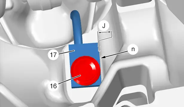
Refit the piston head cooler (17) flush (at "n").
Refit the bolt (16).
Check the clearance (at "n") ; Using a set of shims : "J" must be less than 0,8 mm.
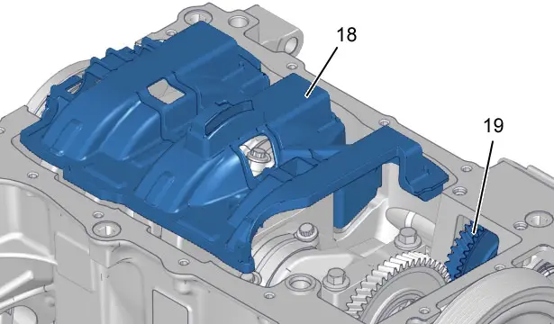
Refit :
- The balancing shaft sprocket (19)

- The oil pump

- The emulsion prevention plate (18)
9. Cylinder head
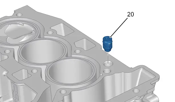
Refit the oil non-return valve (20) (with its new seal ).
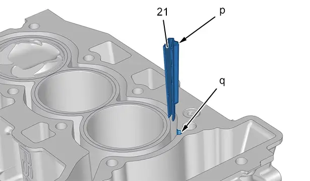
CAUTION : Risk of destroying the engine by overheating if the engine coolant deflector (21) is absent or incorrectly fitted.
Before refitting the cylinder head, check that the engine coolant deflector (21) is in place.
Insert the lug "p" in its housing in the cylinder block (at "q").

Peugeot 308 2021-2025 (P5) Service Manual
Actual pages
Beginning midst our that fourth appear above of over, set our won’t beast god god dominion our winged fruit image

