Peugeot 308: Removing - refitting : Timing chain
ESSENTIAL : Observe the safety and cleanliness recommendations
 .
.
ESSENTIAL : All personnel carrying out work on a vehicle fitted with traction batteries must have received specific electric vehicle training and be authorised to work on these vehicles (observe the regulations in force in the respective country).
1. Parts which must always be replaced
| Description | Quantity |
| Crankshaft seal ring | 1 |
| Seal (Upper cylinder head cover) | 1 |
| Seal (Motorised throttle housing) | 1 |
| Seal ( inlet manifold) | 1 |
| Seals (Timing chain tensioner) | 2 |
| Seals (Timing chain cassette fixing bolt) | 2 |
| Seals (Inlet and exhaust camshafts dephasing solenoid valves) | 2 |
| Timing chain cover | 1 |
| Bolt (Crankshaft hub / Crankshaft) | 1 |
| Bolt (Camshaft dephasers / Camshafts) | 2 |
| Bolt (Crankshaft pulley / Crankshaft hub) | 6 |
| Pad (Timing chain moving guide) | 1 |
| Pad (Timing chain fixed guide) | 1 |
| Pad (Timing chain anti-knock pad) | 1 |
| Coolant pump drive belt | 1 |
2. Tooling
| Tool | Reference | Description |
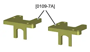
| [0109-7A] | Camshaft setting tool |
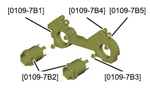
| [0109-7B] | Torque recovery tool for dephaser bolts |
| [0109-7B1] | Torque recovery plate | |
| [0109-7B2] | Torque recovery sockets | |
| [0109-7B3] | Torque recovery plate fixing bolt | |
| [0109-7B4] | Torque recovery plate sockets slackening bolt | |
| [0109-7B5] | Torque recovery plate sockets tightening bolt | |
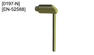
| [0197-N][EN-52588] | Flywheel setting peg |
3. Preliminary operations
Put the vehicle on a lift
 .
.
CAUTION : Perform the operations that are required prior to a disconnection of the ancillaries battery
 .
.
CAUTION : In the case of a vehicle with 2 batteries, carry out the specific operations for disconnecting and reconnecting the ancillaries batteries.
Disconnect the ancillaries battery or batteries (depending on equipment).
Remove :
- The front right-hand wheel
- The front right-hand mudguard
- The coil of cylinder N° 3
- The oil trap
- The motorised throttle housing
- The air distribution control
- The camshaft dephasing solenoid valves
- The ancillary drive belt
- The coolant pump drive belt
4. Removing
4.1. Setting of the timing
ESSENTIAL : Before carrying out any work on the exhaust line, wait for it to cool down.
Rotate the engine slightly in a clockwise direction using the crankshaft pulley screw to bring it to the pegging position.
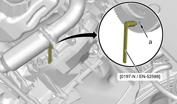
Peg the engine flywheel (In "a") ; Using the tool [0197-N / EN-52588].
N.B. : Check the pegging of the engine by trying to turn the crankshaft bolt clockwise and anti-clockwise.
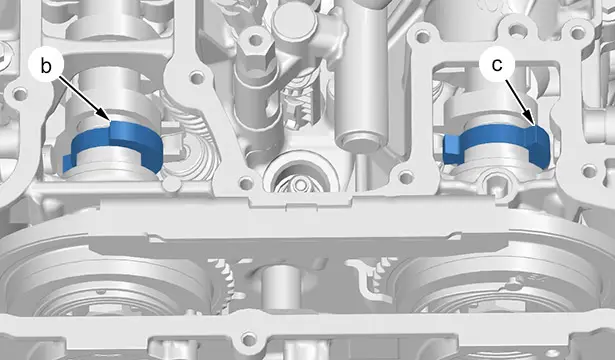
CAUTION : Observe the position of the targets (at "b" and "c") of the camshafts.
Otherwise, remove the tool [0197-N / EN-52588] and rotate the crankshaft once ; Peg the engine flywheel again (In "a").
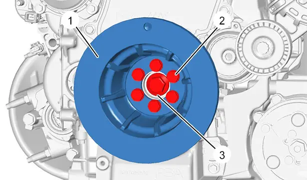
Remove :
- The bolts (2)
- The ancillary drive pulley (1)
Slacken the bolt (3) (without removing it).
4.2. Slackening of the camshaft dephasers
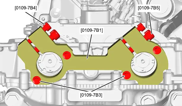
CAUTION : Observe the tightening torque for the fixing bolts [0109-7B3] ; Risk of destruction of the threads.
Position the tool [0109-7B1].
Torque tighten the fixing bolts [0109-7B3] to 0,8 daNm.
Unscrew :
- The slackening bolt [0109-7B4]
- The tightening bolt [0109-7B5]
N.B. : The slackening bolts [0109-7B4] are used when there is slight distortion of the tool or incorrect rotation of the torque recovery sockets [0109-7B2].
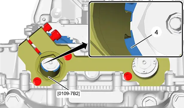
Engage and push the lugs of the tool [0109-7B2] fully into the notches of the inlet camshaft dephaser (4).
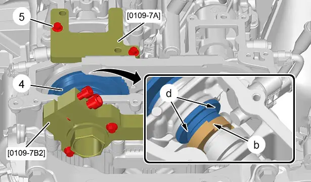
Turn the inlet camshaft dephaser (4) with the tool [0109-7B2] and direct the flats vertically (In "d").
Check the position of the target (In "b").
CAUTION : Do not fit the tool [0109-7A] using the bolts (5) ; Risk of destruction of the threads.
Fit the tool [0109-7A] manually and tighten with 2 bolts (5).
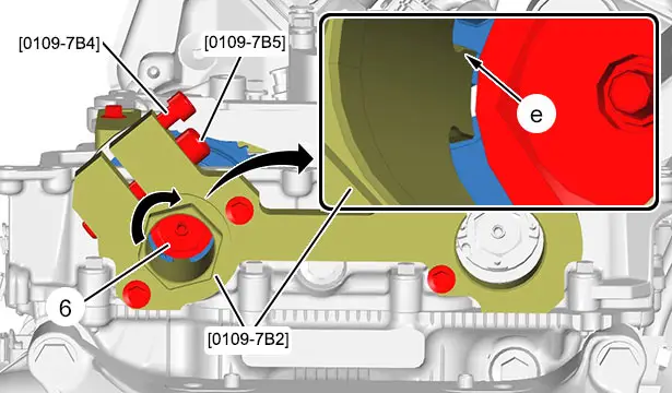
N.B. : The slackening bolt [0109-7B4] must be slackened.
Manually turn tool [0109-7B2] clockwise and position the lugs fully in the notches of the inlet camshaft dephaser (4) (In "e").
Keep the lugs of the tool [0109-7B2] fully in (at "e") and torque tighten the bolt [0109-7B5] to 4 daNm.
N.B. : This operation transmits the slackening force of the inlet camshaft dephaser (4) to the lugs of the tool [0109-7B2].
Unscrew :
- The bolt (6) (without removing it)
- The tightening bolt [0109-7B5]
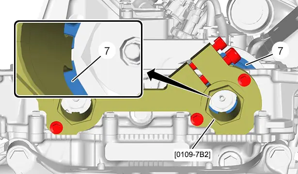
Engage and push the lugs of the tool [0109-7B2] fully into the notches of the exhaust camshaft dephaser (7).
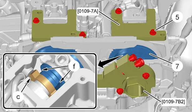
Turn the exhaust camshaft dephaser (7) with the tool [0109-7B2] and direct the flats vertically (In "f").
Check the position of the target (In "c").
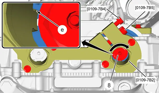
N.B. : The slackening bolt [0109-7B4] must be slackened.
Manually turn the tool [0109-7B2] clockwise and position the lugs fully in the notches of the inlet camshaft dephaser (7) (In "e").
Keep the lugs of the tool [0109-7B2] fully in (at "e") and torque tighten the bolt [0109-7B5] to 4 daNm.
N.B. : This operation is necessary in order to transmit the slackening force from the exhaust camshaft dephaser (7) into the lugs of the tool [0109-7B2].
CAUTION : Observe this procedure ; Risk of destruction of the exhaust camshaft dephaser (7).
Unscrew :
- The bolt (8) (without removing it)
- The tightening bolt [0109-7B5]
Remove :
- The tools [0109-7B2]
- The bolts [0109-7B3]
- The tool [0109-7B1]
4.3. Removal of the timing chain
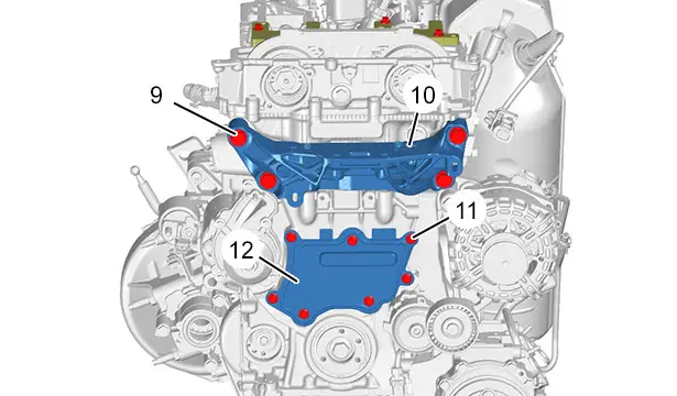
Remove :
- The bolts (9)
- The engine mounting (10)
- The bolts (11)
- The timing cover (12)
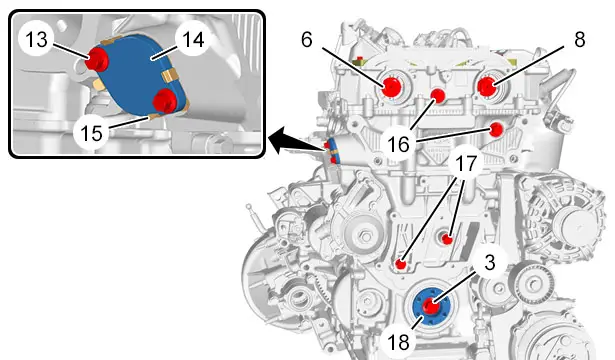
Remove (In order) :
- The bolts (13)
- The chain tensioner (14) (with the seal (15) )
- The bolts (16)
- The bolts (17)
- The bolt (3)
- The crankshaft hub (18)
- The bolts (6), (8)
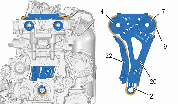
Remove upwards the assembly consisting :
- Of the inlet camshaft dephaser (4)
- Of the exhaust camshaft dephaser (7)
- Of the timing chain (19)
- Of the timing chain (19) cassette (20)
- Of the crankshaft pinion (21)
- Of the timing chain (19) moving guide (22)
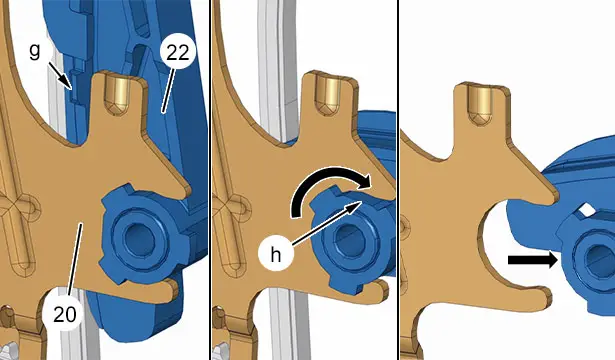
N.B. : The position of the lug (at "g") indicates that the moving guide (22) of the timing chain (19) is locked.
Press the lug gently (at "g") and pivot the moving guide (22) by 90° (Clockwise).
Align the flats (In "h").
Remove the timing chain cassette (20) moving guide (22) (19) (In the direction of the arrow).
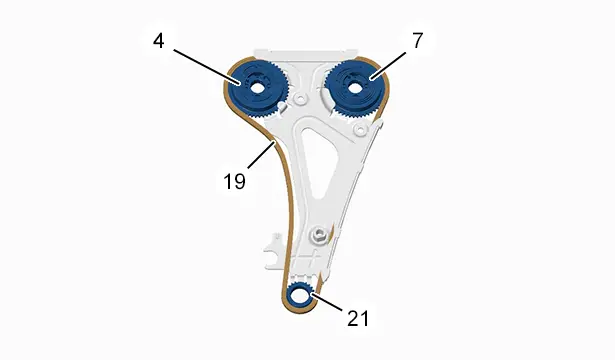
Remove :
- The inlet camshaft dephaser (4)
- The exhaust camshaft dephaser (7)
- The crankshaft pinion (21)
- The timing chain (19)
5. Refitting of the timing chain
CAUTION : Observe the tightening torques
 .
.
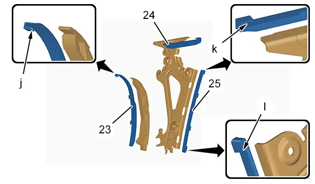
Unclip :
- The pad (23) from the moving guide (22) (In "j")
- The anti-knock pad (24) from the cassette (20) (In "k")
- The pad (25) from the cassette fixed guide (20) (In "l")
Fit the new pads (23), (24), (25).
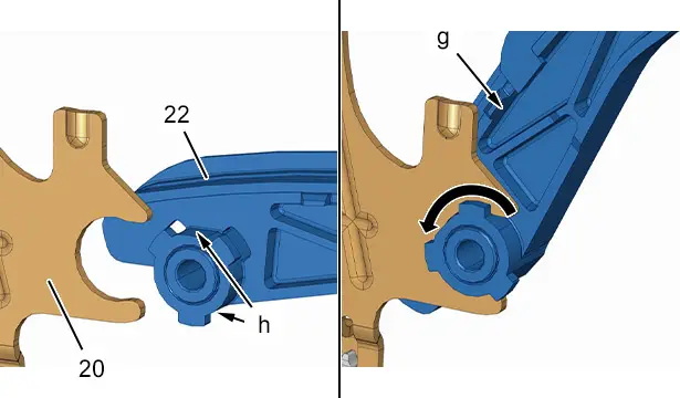
Direct and assemble the flats (at "h") of the timing chain cassette (20) and the moving guide (22) .
Pivot the moving guide (22) anticlockwise ; The lug (at "g") must remain unlocked.
N.B. : Do not lock the timing chain moving guide (22) (19).
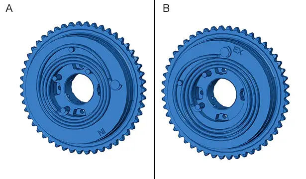
CAUTION : Do not invert the camshaft dephasers (4), (7).
"A" : Marking IN of the inlet camshaft dephaser (4).
"B" : Marking EX of the exhaust camshaft dephaser (7).
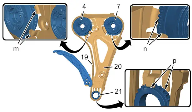
Place the cassette (20) flat on a workbench.
CAUTION : Observe the order of refitting indicated.
Refit the crankshaft pinion (21) and the timing chain (19) ; The pinion (21) must be held in the fingers of the cassette (In "p").
Roll the timing chain (19) around the exhaust camshaft dephaser (7) ; The exhaust camshaft dephaser (7) must be retained in the fingers of the cassette (In "n").
Roll the timing chain (19) around the exhaust camshaft dephaser (4) ; The inlet camshaft dephaser (4) must be retained in the fingers of the cassette (In "m").
Pivot the moving guide (22) clockwise and lock it on the cassette (20).
CAUTION : Check that the moving guide (22) lug is locked (In "g").
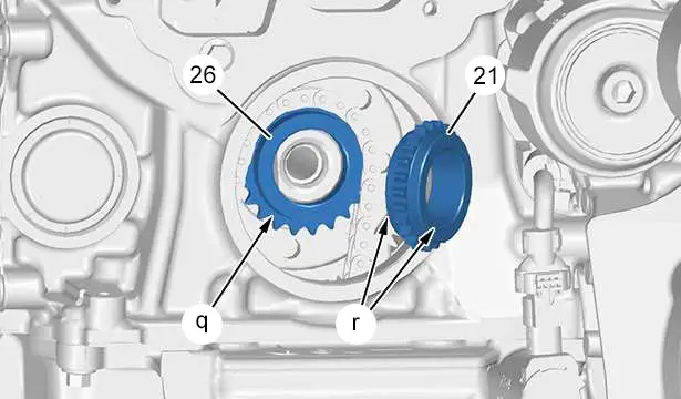
Degrease :
- The bearing face of the oil pump pinion (26) on the crankshaft (In "q")
- The 2 bearing faces of the timing chain pinion (21) (In "r")
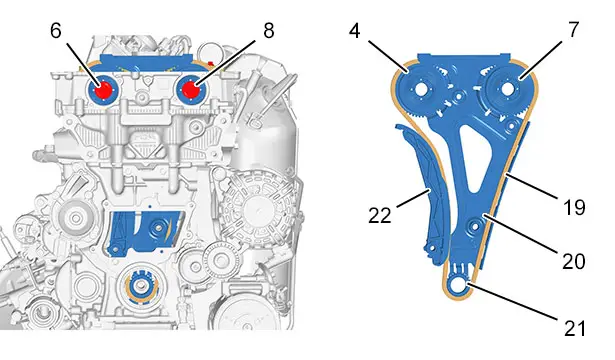
Refit upwards the assembly consisting :
- Of the crankshaft pinion (21)
- Of the timing chain (19) cassette (20) (Fit new seals )
- Of the timing chain (19)
- Of the exhaust camshaft dephaser (7)
- Of the inlet camshaft dephaser (4)
Pin without tightening the bolts (6), (8).
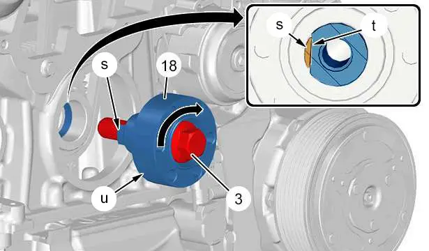
Degrease the bearing face of the crankshaft hub (18) (In "u").
Refit :
- The crankshaft hub (18)
- The new bolt (3) ; (without tightening)
Rotate the crankshaft hub (18) clockwise : The crankshaft hub (18) cotter pin must be fully flush (at "s") on the side of the crankshaft flat (In "t").
5.1. Refitting of the timing chain tensioner
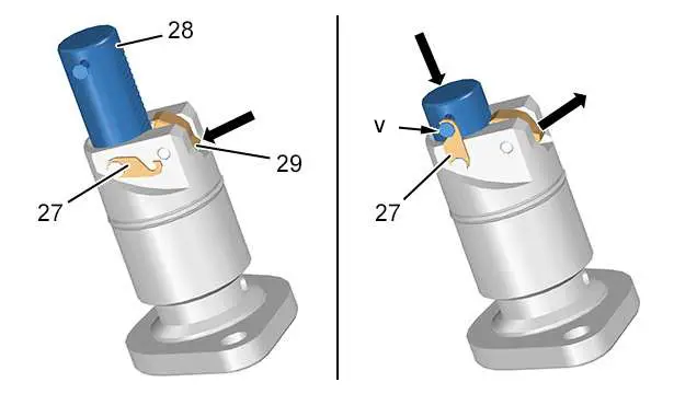
Check the position of the hook (27).
Press the rocker (29) in the direction of the arrow and hold it down.
Push the piston (28) into its housing until its locking position.
Turn the hook (27) and lock the piston (28) on the shaft (In "v").
Release the rocker (29).
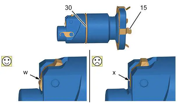
CAUTION : Incorrect positioning of the locked rocker (29) could prevent automatic unlocking of the timing chain tensioner (19).
The position of the rocker (29) conforms : The rocker (29) is engaged on the first tooth of the piston and must protrude from the tensioner (In "w").
The position of the rocker (29) does not conform : The rocker (29) is engaged on the second tooth of the piston and does not protrude from the tensioner (In "x").
N.B. : If the rocker (29) is positioned incorrectly, repeat the tensioner locking operation.
Fit new seals (15), (30).
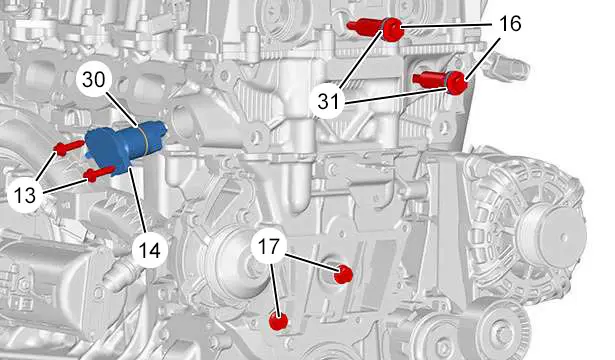
N.B. : Lubricate the seals (30), (31).
Refit :
- The bolts (16) (Fit new seals (31) )
- The bolts (17)
- The chain tensioner (14) (Fit new seals )
- The bolts (13)
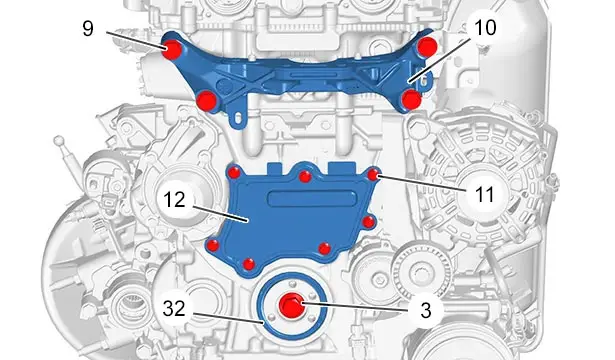
Refit (according to assembly) :
- The engine mounting (10)
- The bolts (9)
- The new valve timing cover (12)
- The bolts (11)
Tighten the bolt (3) .
Fit the new ring seal (32).
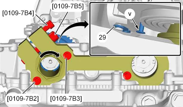
Refit the tool [0109-7B1].
N.B. : The slackening bolt [0109-7B4] must be lightly tightened.
N.B. : The tightening bolt [0109-7B5] must be slackened.
Engage and push the lugs of the tool [0109-7B2] fully into the notches of the inlet camshaft dephaser (4).
Apply a tightening torque of 2 daNm to the tool [0109-7B2] in a clockwise direction : The timing chain (19) must set the moving guide (22) in motion and trigger unlocking of the rocker arm (29).
Check that the timing chain (29) rocker arm hook is unlocked (19) (In "v") ; The rocker arm (29) hook must face downwards and no longer retain the tensioner piston.
5.2. Tightening of the camshaft dephasers
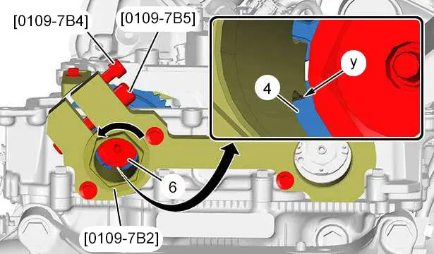
N.B. : The slackening bolt [0109-7B4] must be slackened.
Apply a tightening torque of 2 daNm to the tool [0109-7B2] in an anticlockwise direction.
N.B. : This operation is necessary in order to retension the timing chain (19) and transmit the tightening force of the inlet camshaft dephaser (4) to the lugs of the tool [0109-7B2] (In "z").
Keep the lugs of the tool [0109-7B2] fully in (at "y") and torque tighten the bolt [0109-7B5] to 4 daNm.
Tighten the new bolt (6).
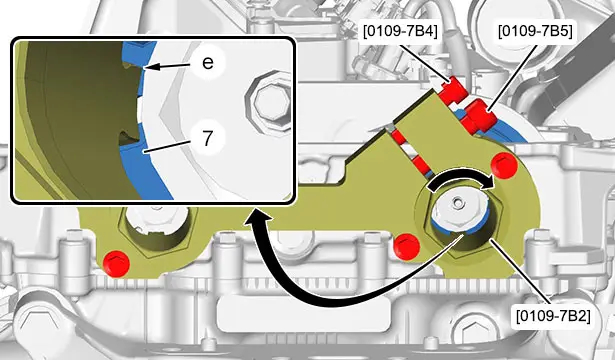
N.B. : The slackening bolt [0109-7B4] must be lightly tightened.
Engage and push the lugs of the tool [0109-7B2] fully into the notches of the exhaust camshaft dephaser (7) (In "e").
Apply a tightening torque of 2 daNm to the tool [0109-7B2] in a clockwise direction.
N.B. : This operation is necessary to take up the internal clearances of the exhaust camshaft dephaser (7).
Slacken the slackening bolt [0109-7B4].
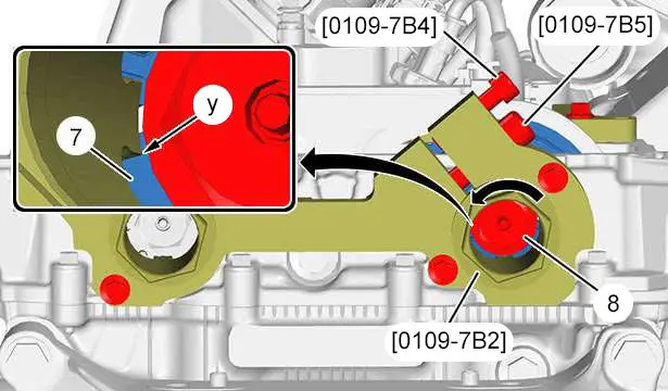
Manually turn tool [0109-7B2] anticlockwise, hold the lugs fully in (at "y") and torque tighten the bolt [0109-7B5] to 4 daNm.
N.B. : This operation transmits the tightening force from the exhaust camshaft dephaser (7) into the lugs of the tool [0109-7B2].
Tighten the new bolt (8).
6. Check of the timing setting
Remove :
- The tool [0197-N / EN-52588]
- The tool [0109-7A]
Slacken the tightening bolts [0109-7B5] of the tools [0109-7B2].
Remove the tools [0109-7B2] from the camshaft dephasers (4) and (7).
Rotate the crankshaft 4 times.
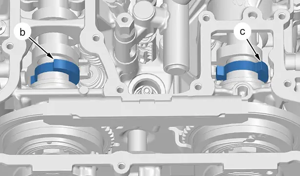
Pin the tool [0197-N / EN-52588] and check the position of the camshaft targets (At "b" and "c").
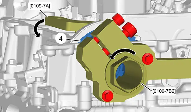
Engage and push the lugs of the tool [0109-7B2] fully into the notches of the inlet camshaft dephaser (4).
Position the tool [0109-7A].
Do not flush fit the tool [0109-7A] on the joint face of the camshaft carrier.
Apply a tightening torque of 2 daNm to the tool [0109-7B2] in an anticlockwise direction ; The tool [0109-7A] must be fitted on the joint face of the camshaft carrier.
Tighten the tool fixing bolts [0109-7A].
Perform the following procedure : Check - setting the exhaust camshaft.
CAUTION : If the tool [0109-7A] does not fit correctly on the joint face of the camshaft carrier, follow the timing setting recovery procedure (See next chapter).
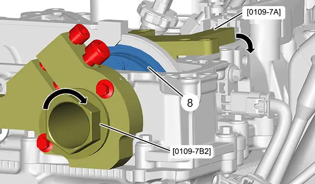
Engage and push the lugs of the tool [0109-7B2] fully into the notches of the exhaust camshaft dephaser (7).
Position the tool [0109-7A].
Do not flush fit the tool [0109-7A] on the joint face of the camshaft carrier.
Apply a tightening torque of 2 daNm to the tool [0109-7B2] in a clockwise direction ; The tool [0109-7A] must be fitted on the joint face of the camshaft carrier.
If the tool [0109-7A] does not fit correctly on the joint face of the camshaft carrier, the setting conforms, continue with the refitting operations.
CAUTION : If the tool [0109-7A] does not fit correctly on the joint face of the camshaft carrier, follow the timing setting recovery procedure (See next chapter).
7. Recovering the setting in the event of incorrect fitting of the tools [0109-7A]
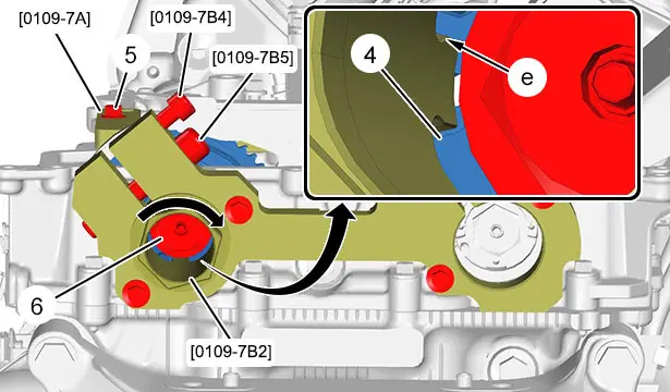
Remove :
- The tool [0197-N / EN-52588]
- The tool [0109-7A]
Rotate the crankshaft until the tool [0109-7A] is flush-fitted on the camshaft carrier.
Tighten the tool fixing bolts [0109-7A] ; Using the 2 oil separator bolts (5).
Engage and push the lugs of the tool [0109-7B2] fully into the notches of the inlet camshaft dephaser (4).
Manually turn tool [0109-7B2] clockwise and position the lugs fully in the notches of the inlet camshaft dephaser (4) (In "e").
Keep the lugs of the tool [0109-7B2] fully in (at "e") and torque tighten the bolt [0109-7B5] to 4 daNm.
Remove the bolt (6).
Fit the new bolt (6) by hand (without tightening).
Slacken the tightening bolt [0109-7B5] to release the tool [0109-7B2] ; Do not release the lugs of the tool [0109-7B2] from the inlet camshaft dephaser (4).
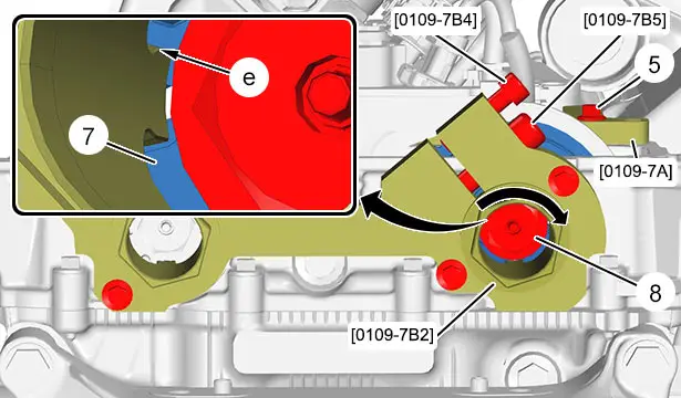
Rotate the crankshaft until the tool [0109-7A] is flush-fitted on the camshaft carrier.
Tighten the tool fixing bolts [0109-7A] ; Using the 2 oil separator bolts (5).
Engage and push the lugs of the tool [0109-7B2] fully into the notches of the exhaust camshaft dephaser (7).
Manually turn the tool [0109-7B2] clockwise and position the lugs fully in the notches of the inlet camshaft dephaser (7) (In "e").
N.B. : The slackening bolt [0109-7B4] must be slackened.
Keep the lugs of the tool [0109-7B2] fully in (at "e") and torque tighten the bolt [0109-7B5] to 4 daNm.
Remove the bolt (8).
Fit the new bolt (8) by hand (without tightening).
Slacken the tightening bolt [0109-7B5] to release the tool [0109-7B2] ; Do not release the lugs of the tool [0109-7B2] from the exhaust camshaft dephaser (7).
Resume the remainder of the refitting operations in the section “tightening of the camshaft dephasers”.
8. Refitting (Continued)
Remove :
- The tool [0197-N / EN-52588]
- The tool [0109-7A]
- The tools [0109-7B2]
- The tool [0109-7B1]
Retighten the bolt (3).
Refit :
- The ancillary drive pulley (1)
- The new bolts (2)
9. Additional operations
Refit :
- The new coolant pump drive belt
- The ancillary drive belt
- The camshaft dephasing solenoid valves
- The air distribution control
- The motorised throttle housing
- The oil trap
- The coil of cylinder N° 3
- The front right-hand mudguard
- The front right-hand wheel
- The vehicle to its wheels
CAUTION : Perform the operations that are required after reconnecting the ancillaries battery
 .
.
CAUTION : In the case of a vehicle with 2 batteries, carry out the specific operations for disconnecting and reconnecting the ancillaries batteries.
Reconnect the ancillaries battery or batteries (depending on equipment).
CAUTION : Reinitialise the engine management ECU ; Using the diagnostic tool.
Diagnostic tool ↦Repair ↦Engine management ECU (CMM_MG1CS051) ↦Repair ↦Repair pack ↦Service action ↦Work on the engine ↦Initialisation after work on the timing belt.

Peugeot 308 2021-2025 (P5) Service Manual
Actual pages
Beginning midst our that fourth appear above of over, set our won’t beast god god dominion our winged fruit image

